
Module for use with a monitoring system and method of assembling same

a monitoring system and module technology, applied in the direction of cross-talk/noise/interference reduction, electrical apparatus construction details, printed circuit grounding, etc., can solve the problems of known monitoring systems being susceptible to externally generated electromagnetic radiation, known machines may exhibit vibration or other abnormal behavior,

Active Publication Date: 2015-07-28
BAKER HUGHES HLDG LLC
View PDF13 Cites 0 Cited by
  • Summary
  • Abstract
  • Description
  • Claims
  • Application Information

AI Technical Summary

Problems solved by technology

Known machines may exhibit vibrations or other abnormal behavior during operation.
However, during transmission of such high-speed signals, unwanted electromagnetic radiation may be generated.
Additionally, known monitoring systems may be susceptible to externally-generated electromagnetic radiation.

Method used


Image

  • Module for use with a monitoring system and method of assembling same
  • Module for use with a monitoring system and method of assembling same
  • Module for use with a monitoring system and method of assembling same

Examples


Embodiment Construction

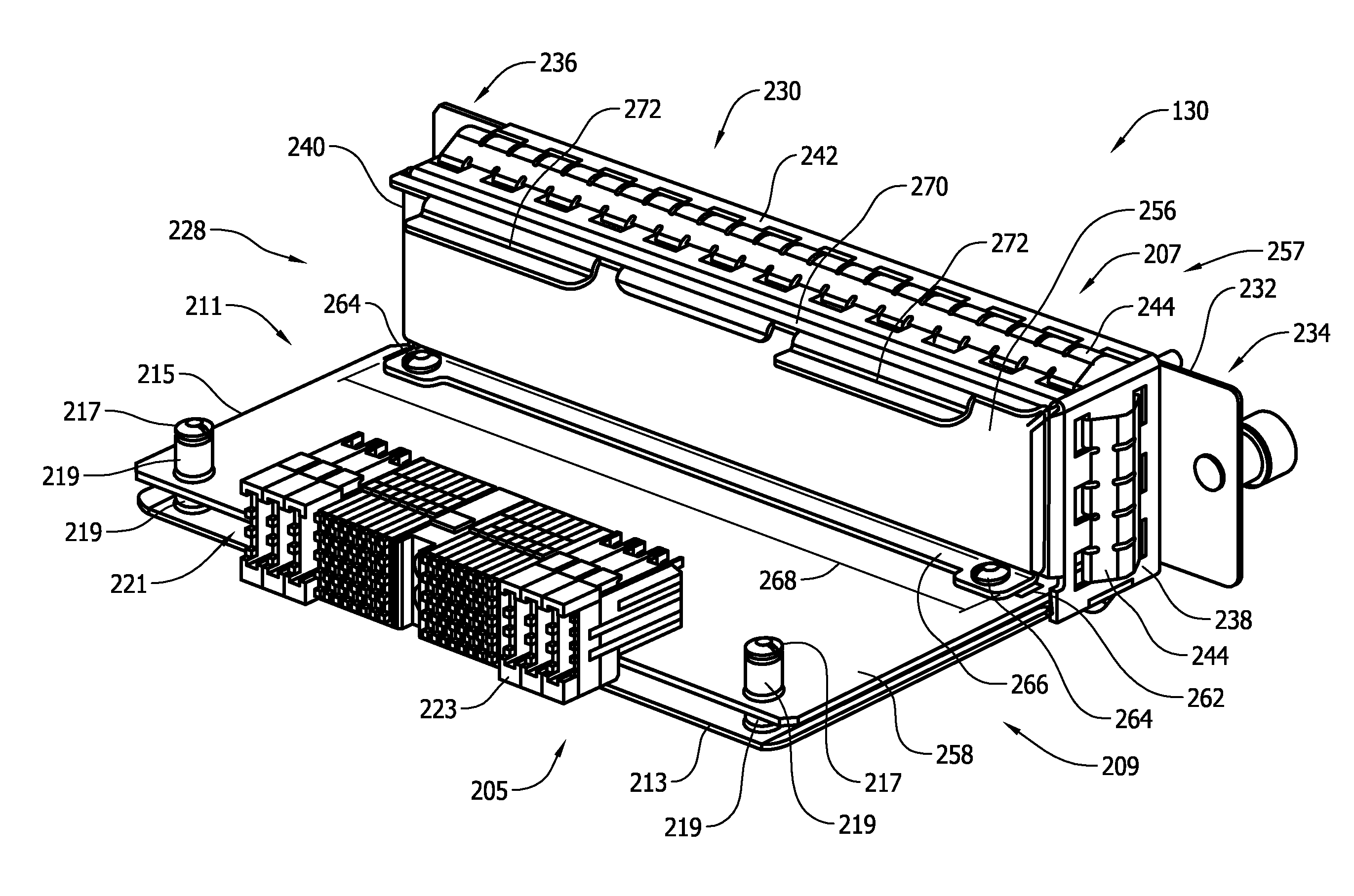
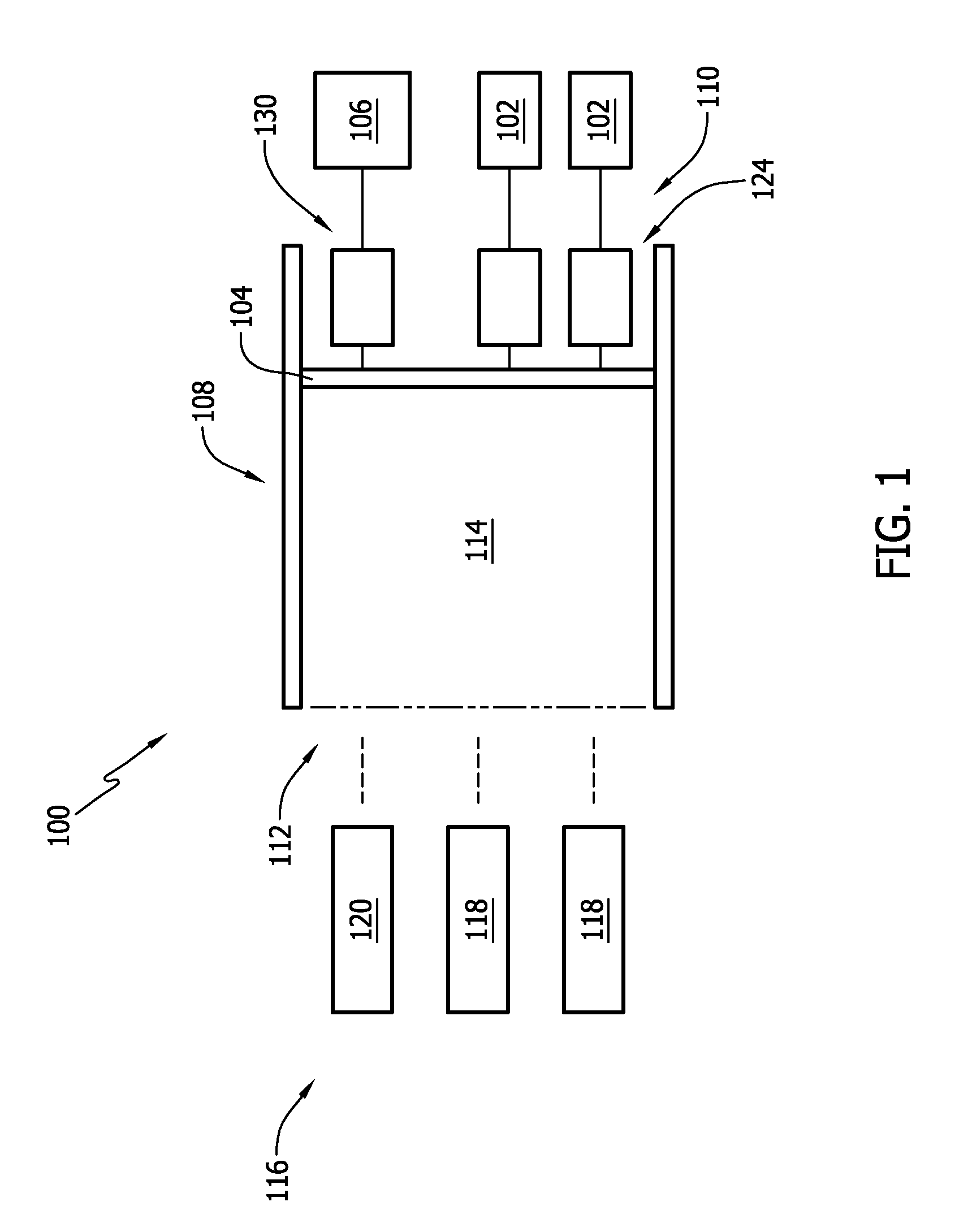
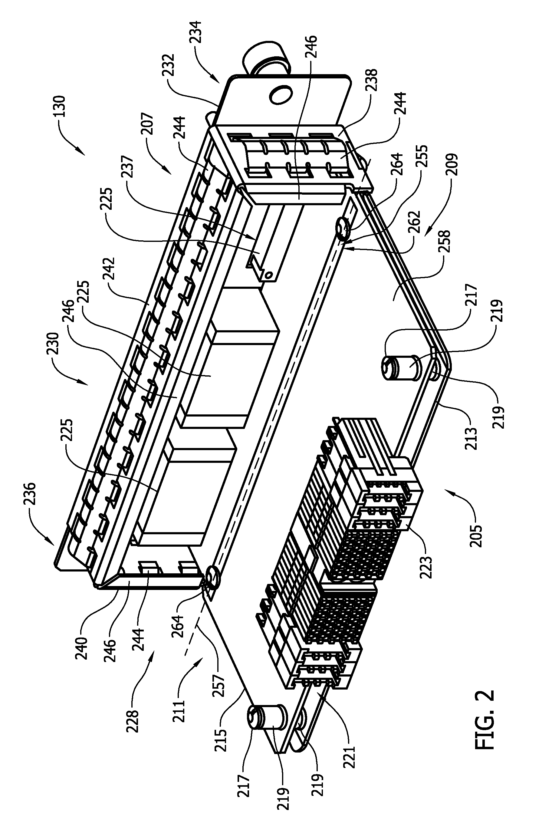
[0013]FIG. 1 is a schematic view of an exemplary machine monitoring system 100 that may be used to monitor the operation of a machine (not shown). In the exemplary embodiment, monitoring system 100 monitors at least one operating condition of one or more machines using one or more transducers 102 or other sensors. More specifically, in the exemplary embodiment, a plurality of transducers 102 are coupled to a system backplane 104 that receives signals from transducers 102 that are indicative of measured and / or detected operating conditions of the machine and / or of one or more components of the machine. Moreover, in the exemplary embodiment, monitoring system 100 receives power from a power supply 106 coupled to system backplane 104. Alternatively, monitoring system 100 may receive power from any suitable power source that enables system 100 to function as described herein. In the exemplary embodiment, system backplane 104 includes a monitoring system bus (not shown in FIG. 1) that in...


PUM

PropertyMeasurementUnit
electromagneticaaaaaaaaaa
rotational speedaaaaaaaaaa
speedaaaaaaaaaa

Abstract

A module for use with a monitoring system is provided. The module includes a circuit board that includes a plurality of ground planes. At least two of the plurality of ground planes are coupled using a plurality of vias. The module further includes a copper pour coupled to the circuit board adjacent to the plurality of vias. The module further includes a housing that includes a dam wall that is coupled to the copper pour.

Description

BACKGROUND OF THE INVENTION[0001]The present application relates generally to monitoring systems and, more particularly, to a monitoring system module including electromagnetic interference protection.[0002]Known machines may exhibit vibrations or other abnormal behavior during operation. One or more sensors may be used to measure and / or monitor such behavior and to determine, for example, an amount of vibration exhibited in a motor drive shaft, a rotational speed of the motor drive shaft, and / or any other suitable operational characteristic of an operating machine or motor. Often, sensors are coupled to a monitoring system that includes a plurality of monitors. At least some known monitoring systems receive signals representative of measurements from one or more sensors, and in response, perform at least one processing step on the signals, prior to transmitting the modified signals to a diagnostic platform that displays the measurements to a user in a format usable by the user.[000...

Claims


Application Information

Patent Timeline
Patent Type & Authority Patents(United States)
IPC IPC(8): H05K1/14H05K1/02
CPCH05K1/0218H05K1/0215Y10T29/49117Y10T29/49147
Inventor COHEN, MITCHELL DEANNIKKELS, ROBERT RONALDSUMMERS, SEAN KELLY
Owner BAKER HUGHES HLDG LLC
Learn More