Methods and systems for destabilizing foam in equipment downstream of a submerged combustion melter

a technology of combustion melter and foam destabilization system, which is applied in the direction of glass making apparatus, manufacturing tools, lighting and heating apparatus, etc., can solve the problems of high turbulence, rapid melting of glass batch, and the tendency of foam formed in the scm to be resistant to destruction or even reduction, and achieve the effect of increasing the turbulence of the molten mass

Active Publication Date: 2015-08-04
JOHNS MANVILLE CORP
View PDF335 Cites 35 Cited by
  • Summary
  • Abstract
  • Description
  • Claims
  • Application Information

AI Technical Summary

Problems solved by technology

The introduction of high flow rates of oxidant and fuel into the molten glass, and the expansion of the gases cause rapid melting of the glass batch and much turbulence, and possibly foaming.
Although this is still desired for the most part, one drawback to this strategy in known submerged combustion systems and methods of melting glass-forming materials using an SCM is the tendency of the foam formed in the SCM to be resistant to destruction or even reduction.
This may cause one or more problems in equipment downstream of the SCM, for example, glass conditioning and transport may be hindered as the foam layer may serve as an insulator and may limit the amount of energy capable of being transferred to the molten glass to maintain its temperature.
In addition, the foam may be destructive of forehearth heating systems and construction materials.
In extreme cases, the foam may cause systems to require shutdown, maintenance and may result in a process upset.
Attempts to reduce the foam through process adjustments, summarized in “Glass Industry of the Future”, U.S. Dept. of Energy, Report 02-GA50113-03, Sep. 30, 2008, such as use of helium and steam to scavenge and consolidate bubbles, sonic methods to consolidate bubbles, vacuum to increase bubble size, and centrifugal force have not met with complete success in reducing foam to an acceptable amount.

Method used


Image

  • Methods and systems for destabilizing foam in equipment downstream of a submerged combustion melter
  • Methods and systems for destabilizing foam in equipment downstream of a submerged combustion melter
  • Methods and systems for destabilizing foam in equipment downstream of a submerged combustion melter

Examples


embodiment 100

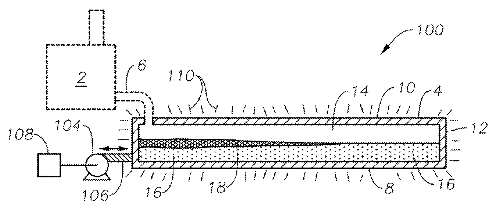
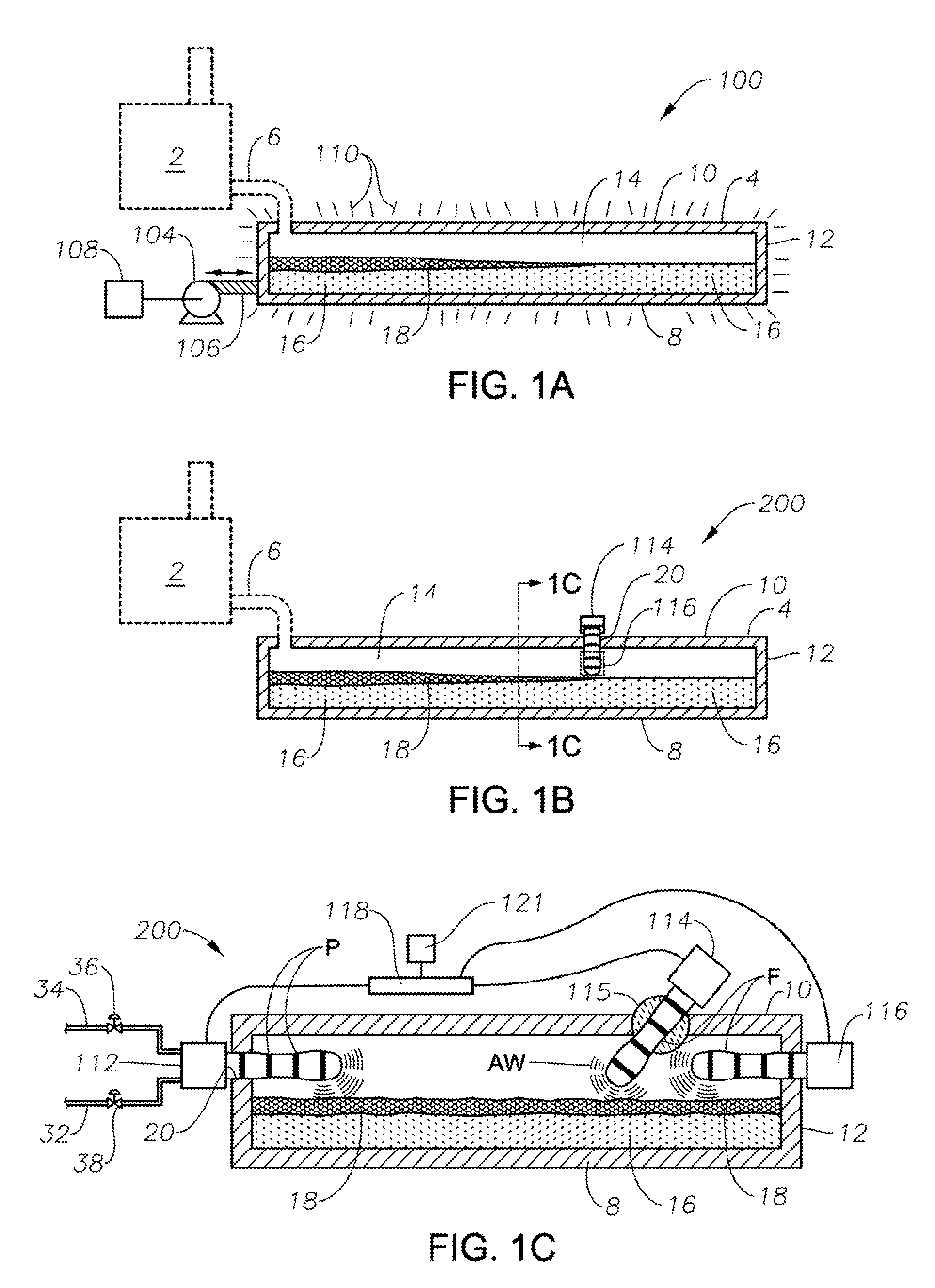
[0039]FIG. 1A is a schematic side elevation view, partially in cross-section, of one system embodiment 100 in accordance with the present disclosure. In all of the drawing figures where an SCM is illustrated, such as at 2 in FIG. 1A, the SCM is illustrated in dashed lines, indicating that the SCM is not, strictly speaking, a part of every system and method of the present disclosure. However, certain systems and methods may be described as comprising an SCM and one or more downstream apparatus receiving flow of molten glass and foam from the SCM. Molten glass and foam produced in SCM 2 flow into a forehearth or other downstream apparatus 4 via a melter exit structure 6, also illustrated in dashed lines. Downstream apparatus 4 comprises in this embodiment a floor 8, a roof 10, and a sidewall structure 12 connecting floor 8 and roof 10, and these components define an internal space 14 that confines a flowing or non-flowing mass of molten glass 16 having a foam layer 18 generally on a t...

embodiment 200

[0044]In embodiment 200, burners 112, 114, and 116 may be high- or low-momentum detonation combustion burners, and the combustion products or flames do not directly impinge or touch foam layer 18 to de-stabilize the foam, but rely on acoustic wave forces as described.

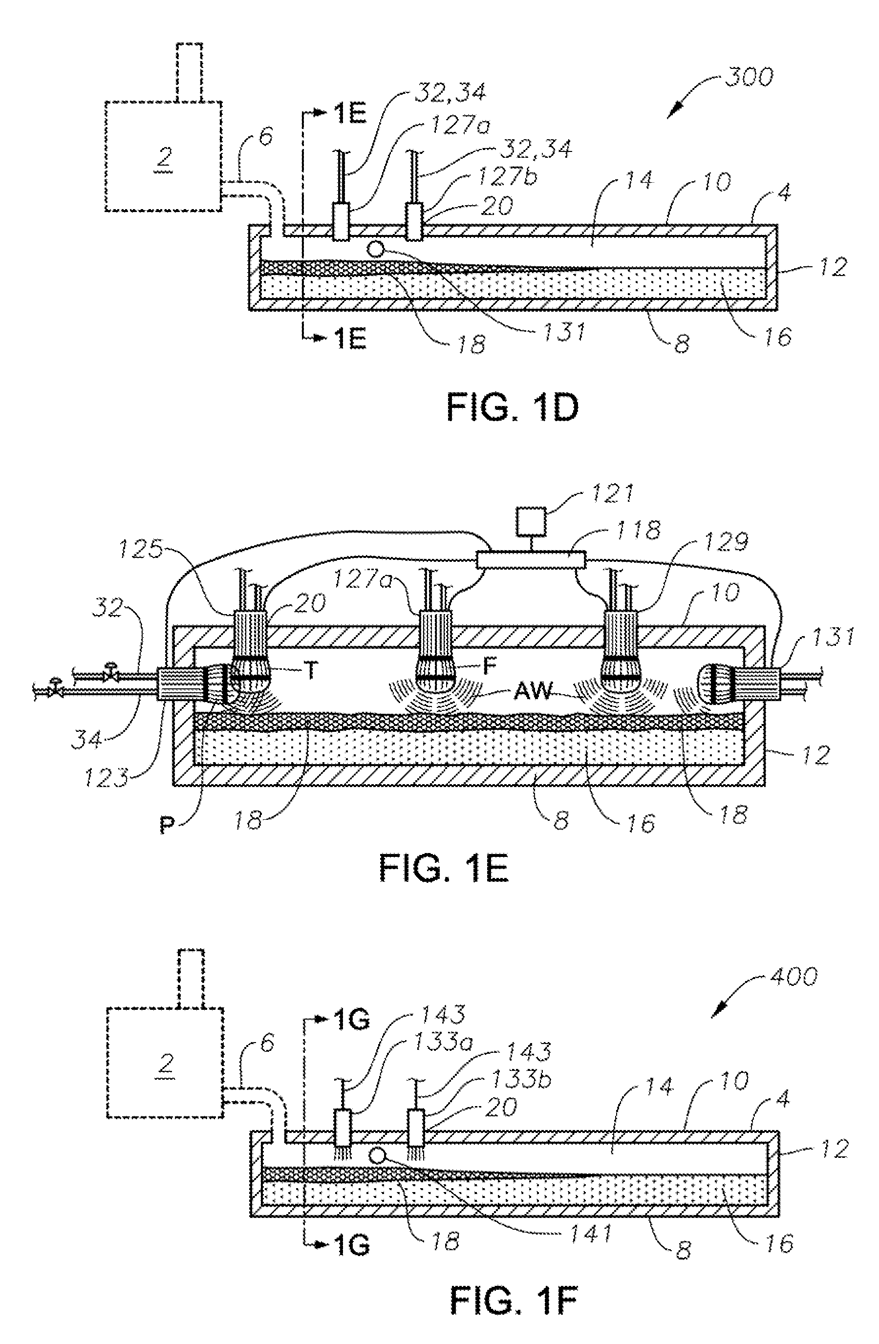
[0045]Another embodiment including one or more acoustic wave force generating apparatus is embodiment 300 illustrated schematically in FIGS. 1D and 1E, which may include one or more pulsed detonation engines (PDE) 123, 125, 127, 129, and 131 positioned in corresponding apertures 20 in wall 12 and / or roof 10 of downstream apparatus 4. FIG. 1D illustrates two PDEs 127a, 127b, spaced apart longitudinally along a central longitudinal axis of downstream apparatus 4. PDEs may have many constructions, but are essentially single-pipe burners having a source of fuel and a source of oxidant attached near a rear end of pipe or conduit, sometimes referred to as a barrel. As illustrated schematically in FIGS. 1D and 1E, PDEs may be ...

embodiment 400

[0046]Yet another embodiment including one or more acoustic wave force generating apparatus is embodiment 400 illustrated schematically in FIGS. 1F and 1G, which includes one or more audio speaker drivers 133, 135, 137, 139, and 141 positioned in corresponding apertures 20 in wall 12 and roof 10 of downstream apparatus 4. In certain embodiments wires 143 may connect the drivers and speakers to a controller 118 having capability of varying frequency and / or amplitude of the speaker output using a separate device 121. Controller 118 may include an amplifier, or the amplifier may be present as a separate component. In certain embodiments the speaker drivers may be wirelessly electronically connected to controller 118 and / or device 121. As illustrated schematically in FIGS. 1F and 1G, speaker drivers may be positioned in multiple longitudinal and transverse positions in downstream apparatus 4, examples being the relative longitudinal positions of speaker drivers 133a and 133b, and the re...


PUM

PropertyMeasurementUnit
velocityaaaaaaaaaa
velocityaaaaaaaaaa
temperatureaaaaaaaaaa

Abstract

Methods and systems for de-stabilizing foam produced in submerged combustion melters. A molten mass of glass and bubbles is flowed into an apparatus downstream of a submerged combustion melter. The downstream apparatus includes a floor, a roof and a wall connecting the floor and roof, but is devoid of submerged combustion burners and other components that would increase turbulence of the molten mass. The molten mass has foam on at least a portion of a top surface of the molten mass. Certain methods include imposing a de-stabilizing force directly to the foam or to the molten mass and foam, where the de-stabilizing force may be a vibratory force, an acoustic wave force, a particulate-based force, or a non-particulate-based mechanical force. Systems for carrying out the methods are described.

Description

CROSS-REFERENCE TO RELATED APPLICATIONS[0001]This application may be related to the following United States non-provisional patent applications assigned to the assignee of the present application which are all incorporated by reference herein: Ser. No. 12 / 817,754, filed Jun. 17, 2010 (U.S. Pat. No. 8,769,992); Ser. Nos. 13 / 267,990, 13 / 268,028 (U.S. Pat. No. 8,875,544), Ser. No. 13 / 268,098 (U.S. Pat. No. 8,707,740), and Ser. No. 13 / 268,130, all four filed Oct. 7, 2011; Ser. No. 13 / 458,211, filed Apr. 27, 2012; Ser. No. 13 / 493,170 (U.S. Pat. No. 8,707,739) and Ser. No. 13 / 493,219, both filed Jun. 11, 2012; Ser. No. 13 / 540,771, filed Jul. 3, 2012; and Ser. Nos. 13 / 633,998; 13 / 633,979; 13 / 644,039; and 13 / 644,058, all filed Oct. 3, 2012.BACKGROUND INFORMATION[0002]1. Technical Field[0003]The present disclosure relates generally to the field of combustion furnaces and methods of use to produce glass, and more specifically to methods and systems to destabilize foam in glass handling equipm...

Claims


Application Information

Patent Timeline
Patent Type & Authority Patents(United States)
IPC IPC(8): C03B5/20C03B5/225C03B3/00C03B5/235
CPCC03B3/00C03B5/20C03B5/225C03B5/235C03B5/2356F23C99/003Y02P40/50
Inventor CHARBONNEAU, MARK WILLIAMHUBER, AARON MORGAN
Owner JOHNS MANVILLE CORP
Why Eureka
Try Eureka