Metal interconnect modeling

a technology of metal interconnects and models, applied in the field of metal interconnect modeling, can solve the problems of a large amount of computing power, and a time-consuming and complicated process for modeling

Inactive Publication Date: 2015-08-04
TAIWAN SEMICON MFG CO LTD
View PDF4 Cites 4 Cited by
  • Summary
  • Abstract
  • Description
  • Claims
  • Application Information

AI Technical Summary

Problems solved by technology

Such modeling is often a time consuming and complicated process.
The equations that are used to model the metal interconnects are relatively complex and thus take a lot of computing power.

Method used


Image

  • Metal interconnect modeling
  • Metal interconnect modeling
  • Metal interconnect modeling

Examples


Embodiment Construction

[0014]It is to be understood that the following disclosure provides many different embodiments, or examples, for implementing different features of the disclosure. Specific examples of components and arrangements are described below to simplify the present disclosure. These are, of course, merely examples and are not intended to be limiting. Moreover, the performance of a first process before a second process in the description that follows may include embodiments in which the second process is performed immediately after the first process, and may also include embodiments in which additional processes may be performed between the first and second processes. Various features may be arbitrarily drawn in different scales for the sake of simplicity and clarity. Furthermore, the formation of a first feature over or on a second feature in the description that follows may include embodiments in which the first and second features are formed in direct contact, and may also include embodime...


PUM


Abstract

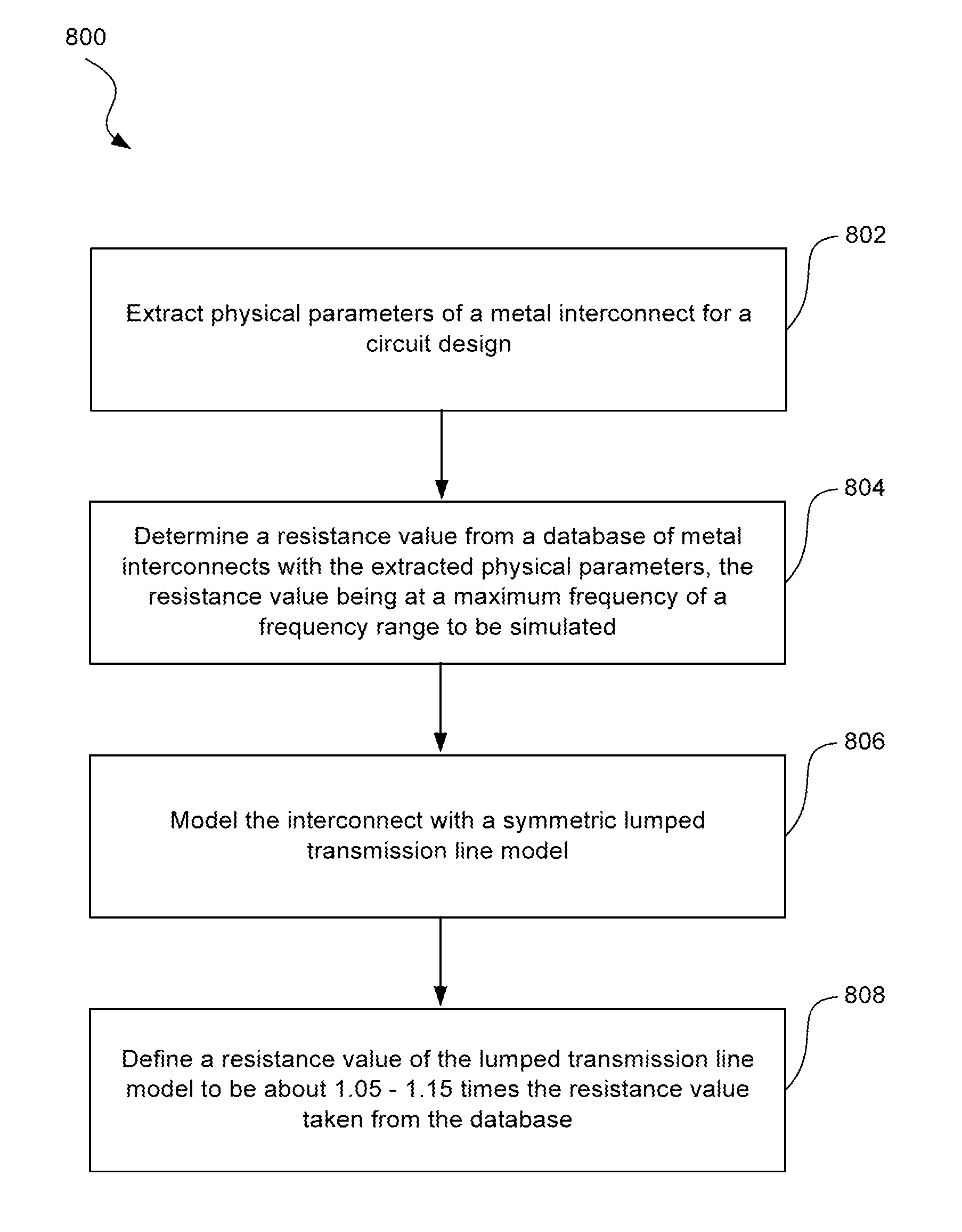
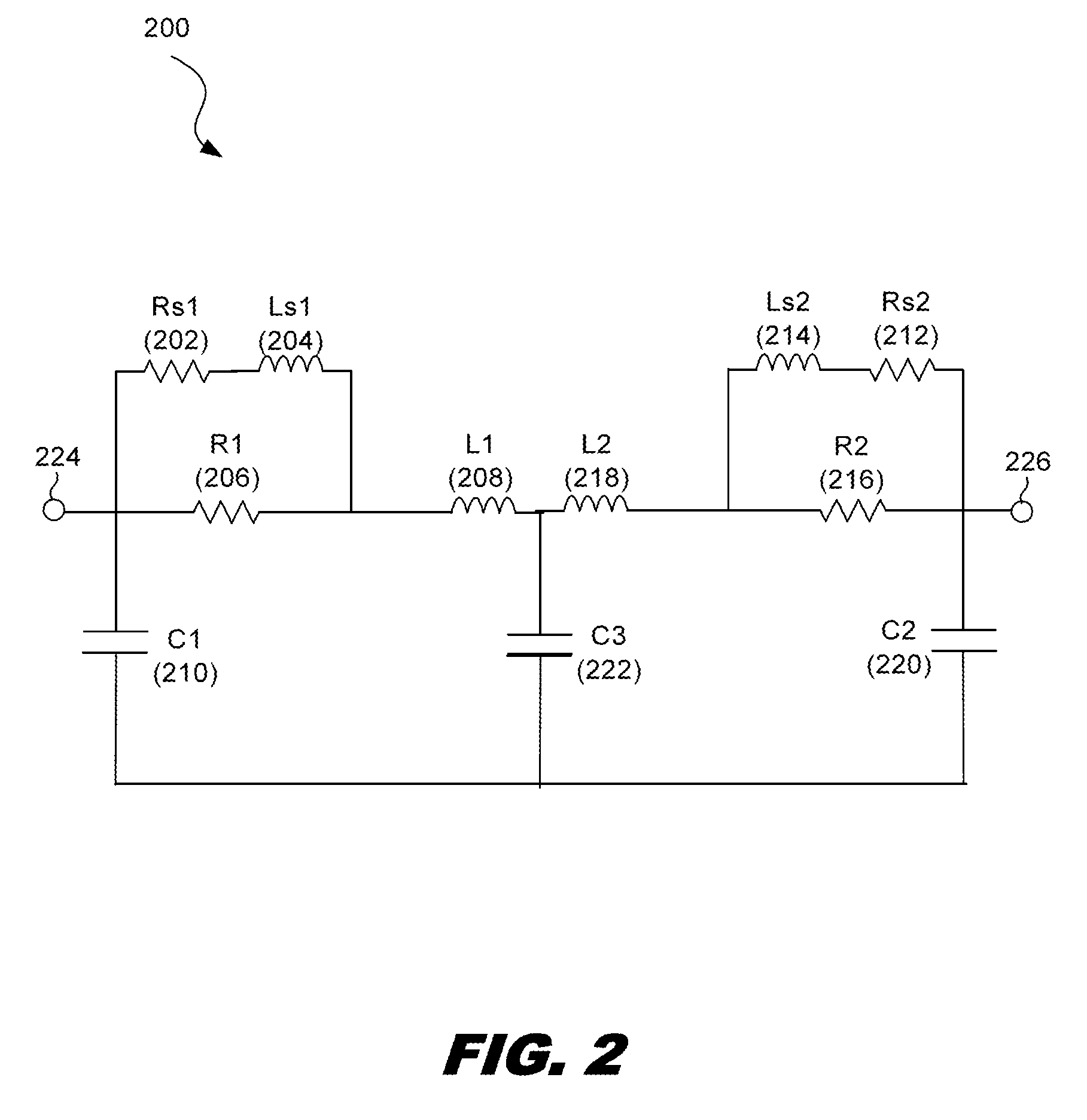
A method for modeling metal routing includes extracting physical parameters of a metal interconnect for a circuit design, determining a resistance value from a database of metal interconnects with the extracted physical parameters, the resistance value being at a maximum frequency of a frequency range to be simulated, modeling the interconnect with a symmetric lumped transmission line model, and defining a resistance value of the lumped transmission line model to be about 1.05-1.3 times the resistance value taken from the database.

Description

PRIORITY DATA[0001]This patent is a non-provisional of U.S. Ser. No. 61 / 775,778 filed Mar. 11, 2013, the entire disclosure of which is hereby incorporated by reference.BACKGROUND[0002]Integrated circuits that are formed into semiconductor substrates include multiple components such as transistors, resistors, and memory elements. These components are typically connected to one another through metal lines that are routed through multiple layers formed onto the substrate. These metal lines are often referred to as metal interconnects.[0003]During the design phase of integrated circuits, the designer often uses a computer drafting tool to design the circuit. The next step is to design the layout of the circuit. The layout indicates how the circuit will be printed onto a substrate. During this phase of the design, it is important to understand how each of the metal interconnects will perform when carrying signals. It is particularly important to understand the behavior of signals passing...

Claims


Application Information

Patent Timeline
Patent Type & Authority Patents(United States)
IPC IPC(8): G06F17/50
CPCG06F17/5036G06F2217/82G06F2119/10G06F30/367G06F30/394
Inventor YEN, HSIAO-TSUNG
Owner TAIWAN SEMICON MFG CO LTD
Why Eureka
Try Eureka