Method for constructing a fracture network grid from a Voronoi diagram

a network grid and voronoi technology, applied in the field of underground deposit development, can solve problems such as flow systems which cannot be solved in actual fractured deposit conditions, and achieve the effect of optimizing the development of the deposi

Active Publication Date: 2015-08-11
INST FR DU PETROLE
View PDF3 Cites 10 Cited by
  • Summary
  • Abstract
  • Description
  • Claims
  • Application Information

AI Technical Summary

Benefits of technology

[0025]One advantage of the invention is that it can be used to solve the flow system in each fracture plane analytically, with the aid of the Voronoi diagram, instead of using finite elements in each plane, as in prior techniques. In fact, these latter techniques lead to flow systems which cannot be solved in actual fractured deposit conditions, as they have 10,000 to 100,000 nodes on each fracture. However, according to the invention, the grids only comprise 3 or 4 nodes at the intersections, enabling millions of fractures to be processed in contrast to the other methods. It is therefore possible to optimize the development of the deposit.
[0030]d) the image of the fluid deposit and a flow simulator are used for optimizing the development of said fluid deposit.
[0031]According to the invention the centers of Voronoi cells can be positioned on the

Problems solved by technology

In fact, these latter techniques lead to flow systems which cannot be solved in actua

Method used


Image

  • Method for constructing a fracture network grid from a Voronoi diagram
  • Method for constructing a fracture network grid from a Voronoi diagram
  • Method for constructing a fracture network grid from a Voronoi diagram

Examples


Embodiment Construction

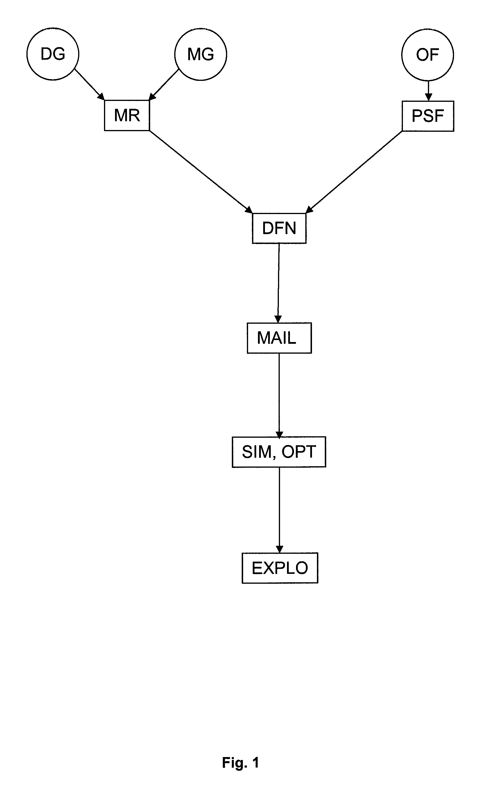
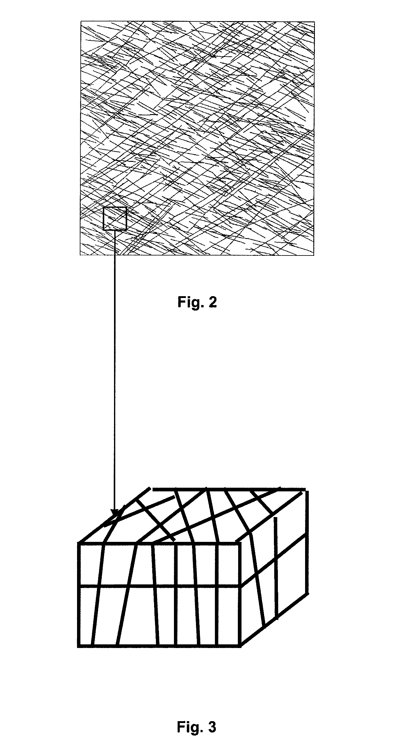
[0043]The method according to the invention for optimizing the development of a deposit, using the method according to the invention of constructing a fracture network grid, comprises five steps with the first four being implemented by a computer, as illustrated in FIG. 1 in which:[0044]Step 1 is a discretiazation of the deposit into a set of grid cells (MR);[0045]Step 2 is a modeling of the fracture network by a discrete fracture model (DFN);[0046]Step 3 is a construction of a grid of the discrete fracture model (MAIL);[0047]Step 4 is a simulation of fluid flows (SIM) and optimization of production conditions of the deposit (OPT);[0048]Step 5 is an optimized (global) development of the deposit (EXPLO)

1—Discretization of the Deposit into a Set of Grid Cells (MR)

[0049]For some time the petroleum industry has combined field (in situ) measurements with experimental modeling (performed in the laboratory) and / or numerical modeling (using software). Petroleum deposit modeling thus constit...


PUM


Abstract

Method for optimizing the development of a fluid deposit using a fracture network grid constructed from a Voronoi diagram.
Based on observations of the deposit a discrete fracture network is constructed in which each fracture is represented by an isotropic polygonal finite plane in terms of its dynamic properties, a plane comprising segments of intersection with other network fractures. A Voronoi diagram is constructed on each fracture plane by positioning Voronoi cell centers on the segments of intersection, and the transmissivities are calculated between centers of neighboring cells from the ratio between the surface area of the neighboring cells and the distance between the neighboring cells. The cells and transmissivities can then be used to construct an image of the fluid deposit. Finally, this image and a flow simulator are used to optimize the development of the fluid deposit.

Description

CROSS REFERENCE TO RELATED APPLICATION[0001]Reference is made to French Patent Application Serial No. 11 / 01686, filed on Jun. 2, 2011, which application is incorporated herein by reference in its entirety.BACKGROUND OF THE INVENTION[0002]1. Field of the Invention[0003]The present invention relates to the development of underground deposits, such as hydrocarbon deposits comprising a fracture network.[0004]2. Description of the Prior Art[0005]The petroleum industry, and more precisely petroleum deposit exploration and development, require that knowledge of the underground geology is as perfect as possible to efficiently provide an evaluation of reserves, a modeling of production or development management. In fact, determining the location of a production well or an injection well, the composition of the drilling mud, the completion characteristics, choosing a method of recovering hydrocarbons (such as water injection for example) and the parameters necessary for the implementation of ...

Claims


Application Information

Patent Timeline
IPC IPC(8): G06G7/48E21B41/00G01V11/00
CPCG01V11/00E21B41/0092G06F30/28E21B41/00
Inventor KHVOENKOVA, NINADELORME, MATTHIEU
Owner INST FR DU PETROLE
Why Eureka
Try Eureka