Optical module and method for producing the same

a technology of optical modules and optical devices, applied in the field of optical modules, can solve the problems of difficult production of optical devices, high cost of conventional optical modules, and difficulty in mounting optical devices, and achieve the effects of convenient mounting of optical devices, low cost, and easy production

Inactive Publication Date: 2015-08-11
HITACHI METALS LTD
View PDF11 Cites 1 Cited by
  • Summary
  • Abstract
  • Description
  • Claims
  • Application Information

AI Technical Summary

Benefits of technology

[0010]This optical module is required to be shortened in a distance between a light-emitting portion or a light-receiving portion of the optical device and a tip of the optical fiber as much as possible, to suppress light loss. To this end, it is preferable to insert the tip of the optical fiber below the optical device (between the optical device and the substrate), to locate the tip of the optical fiber as close to the mirror as possible.
[0012]For example, in the case of mounting the optical fiber after mounting (flip-chip mounting) the optical device on the substrate, it is necessary to insert and fix the optical fiber between the optical device and the substrate under the condition that the optical device is fixed to the substrate with only bumps for flip-chip mounting. As a result, due to the interference of the optical fiber with the optical device during the mounting of the optical fiber, the optical device may slip off the substrate. Incidentally, it is possible to reinforce the connection strength for the optical device to the substrate, thereby prevent the optical device from slipping off the substrate, by filling and curing an underfill resin between the optical device and the substrate after mounting the optical device on the substrate. However, in this case, the underfill resin is likely to flow to the position to mount the optical fiber, and the mounting of the optical fiber per se is likely to be difficult.
[0014]In view of the above circumstances, it is an object of the present invention to provide an optical module and a method for producing the same, which ensures sufficient connection strength for an optical device to a substrate, and low in cost and easy to produce.
[0027](v) The underfill resin preferably reinforces connection strength for the optical device to the substrate.
[0040]According to the present invention, it is possible to provide the optical module and the method for producing the same, which facilitates the mounting of the optical device, and which is easy to produce and low in cost.

Problems solved by technology

However, there is a disadvantage in that the conventional optical module described above is costly, due to the use of the optical waveguide.
However, in such a structure, there is a disadvantage in that it is difficult to mount the optical device and the optical fiber, so that the production thereof is difficult.

Method used


Image

  • Optical module and method for producing the same
  • Optical module and method for producing the same
  • Optical module and method for producing the same

Examples


Embodiment Construction

[0051]Next, preferred embodiments according to the invention will be described below in conjunction with the accompanying drawings.

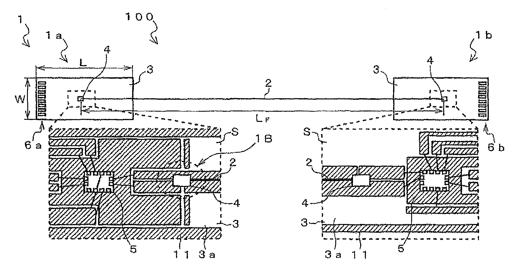
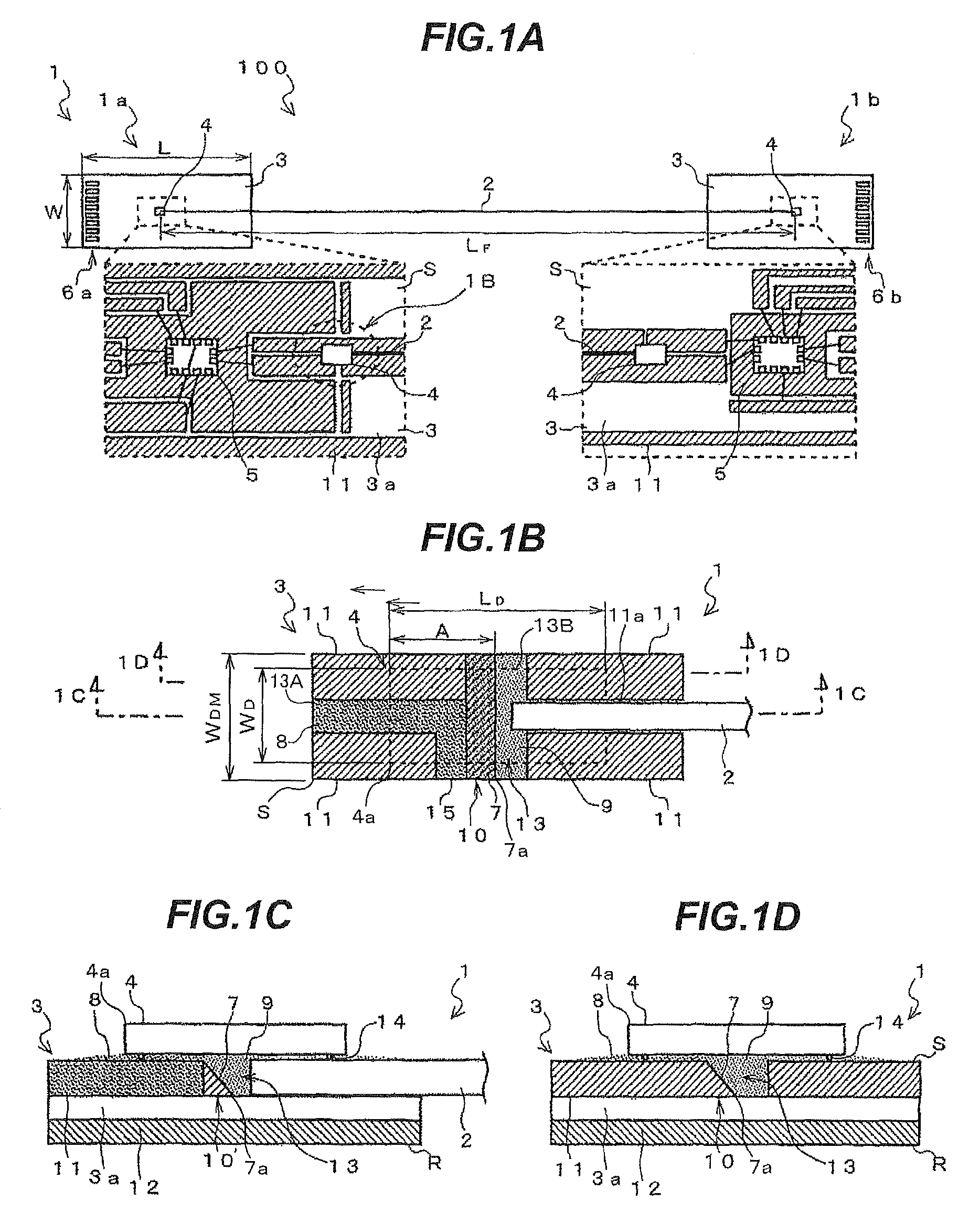
[0052]FIG. 1A is a plan view showing a cable with optical modules and an enlarged view showing an essential portion thereof in one embodiment according to the invention. FIG. 1B is an enlarged view of a portion 1B in FIG. 1A. FIG. 1C is a cross-sectional view taken along line 1C-1C in FIG. 1B. FIG. 1D is a cross-sectional view taken along line 1D-1D in FIG. 1B.

[0053]As shown in FIG. 1A, a cable 100 with optical modules includes and optical fiber 2 and optical modules 1 provided at both ends, respectively, of an optical fiber 2. One end (in the left side of FIG. 1A) of the optical fiber 2 is provided with the transmitting side optical module 1a, while the other end (in the right side of FIG. 1A) of the optical fiber 2 is provided with the receiving side optical module 1b.

[0054]The optical modules 1 (1a, 1b) includes a substrate 3, an optical device 4 com...


PUM

PropertyMeasurementUnit
thicknessaaaaaaaaaa
cladding diameteraaaaaaaaaa
thicknessaaaaaaaaaa

Abstract

An optical module includes a substrate, an optical device including a surface-emitting or -receiving element mounted on a surface of the substrate with a light-emitting or -receiving portion, an optical fiber disposed parallel to the surface of the substrate and in a longitudinal direction of the substrate, a damming member provided between the optical device and the substrate to extend in a width direction of the substrate and dividing a gap between the optical device and the substrate in the longitudinal direction of the substrate into a first portion and a second portion, and a mirror provided at one side surface of the damming member a tip of the optical fiber. The first portion provided on an opposite side to the optical fiber is filled with an underfill resin, and the second portion provided on a side close to the optical fiber is filled with an optical fiber fixing resin.

Description

[0001]The present application is based on Japanese patent application No. 2012-012203 filed on Jan. 24, 2012, the entire contents of which are incorporated herein by reference.BACKGROUND OF THE INVENTION[0002]1. Field of the Invention[0003]The present invention relates to an optical module using an optical device comprising a surface-emitting element or a surface-receiving element. It also relates to a method for producing the optical module.[0004]2. Description of the Related Art[0005]In an optical module using an optical device comprising a surface-emitting element or a surface-receiving element, when the optical device is mounted on a substrate, an optical axis of the optical device is perpendicular to a surface of the substrate. Therefore, in order to optically connect an optical fiber disposed parallel to the surface of the substrate and the optical device together, a mirror is used to rotate the optical axis through 90 degrees.[0006]As this type of optical module, there is con...

Claims


Application Information

Patent Timeline
Patent Type & Authority Patents(United States)
IPC IPC(8): G02B6/36G02B6/12G02B6/42
CPCG02B6/12G02B6/4214G02B6/4239G02B6/4243Y10T29/49993
Inventor YASUDA, HIROKIISHIKAWA, HIROSHIHIRANO, KOUKIYU, JUHYUN
Owner HITACHI METALS LTD
Why Eureka
Try Eureka