System and method for dynamic memory power management

a dynamic memory and power management technology, applied in memory adressing/allocation/relocation, high-level techniques, instruments, etc., can solve the problems of increasing the burden on a limited power supply, pcd still consumes power in the form of sleep current, etc., to reduce the sleep current floor, avoid power consumption, and quickly know the

Active Publication Date: 2015-08-11
QUALCOMM INC
View PDF11 Cites 1 Cited by
  • Summary
  • Abstract
  • Description
  • Claims
  • Application Information

AI Technical Summary

Benefits of technology

[0006]Based on the query, the location of the data in the memory pages of the upper bank is known and can be migrated to memory pages in the lower bank which are identified for receipt of the data. Once migrated, the upper bank may be powered down, thus reducing the sleep current floor by avoiding the power consumption that would otherwise be required to self refresh the upper bank. Advantageously, because the LUT was leveraged to quickly know the specific memory pages in the upper bank which contained data and the specific memory pages in the lower bank which were eligible to receive the data, the time required to conduct the migration is kept at a minimum. As such, one of ordinary skill in the art would recognize that the amount of time the PCD must remain in the sleep state with the powered down upper bank in order to net a power savings is minimized.

Problems solved by technology

Importantly, during these sleep periods, even though in an “idle” mode, the PCD is still consuming power in the form of a sleep current.
Self refresh operations of volatile memory components represent a significant portion of a PCD's sleep current and, as such, are at fault for a significant amount of the power drain that a PCD may experience while in an idle state.
In fact, as the memory in PCDs continues to increase in size, so does the current required to self refresh it, thereby further increasing the burden on a limited power supply.

Method used


Image

  • System and method for dynamic memory power management
  • System and method for dynamic memory power management
  • System and method for dynamic memory power management

Examples


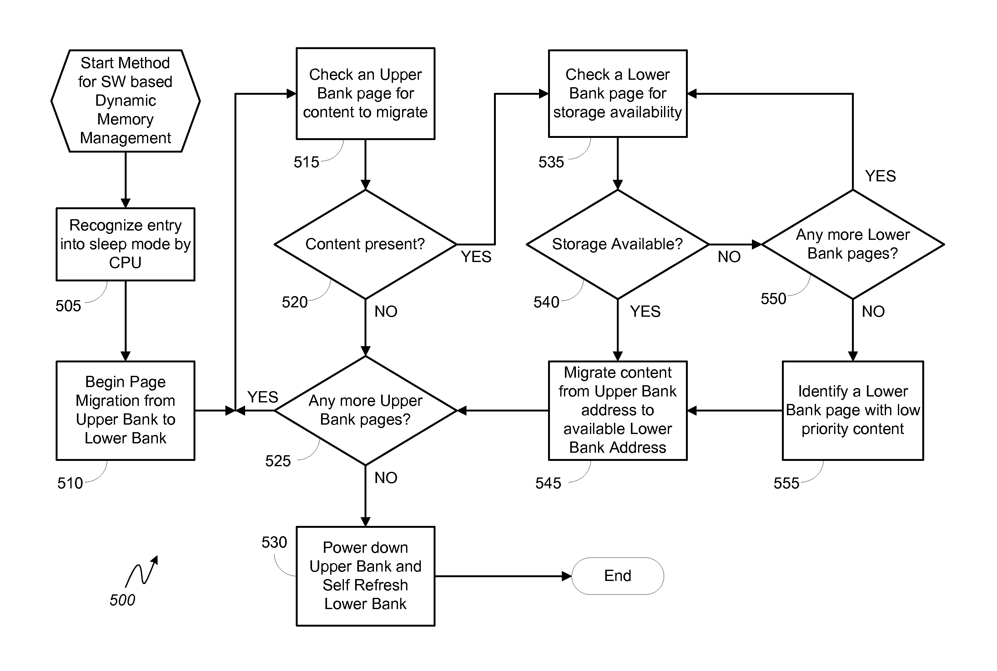
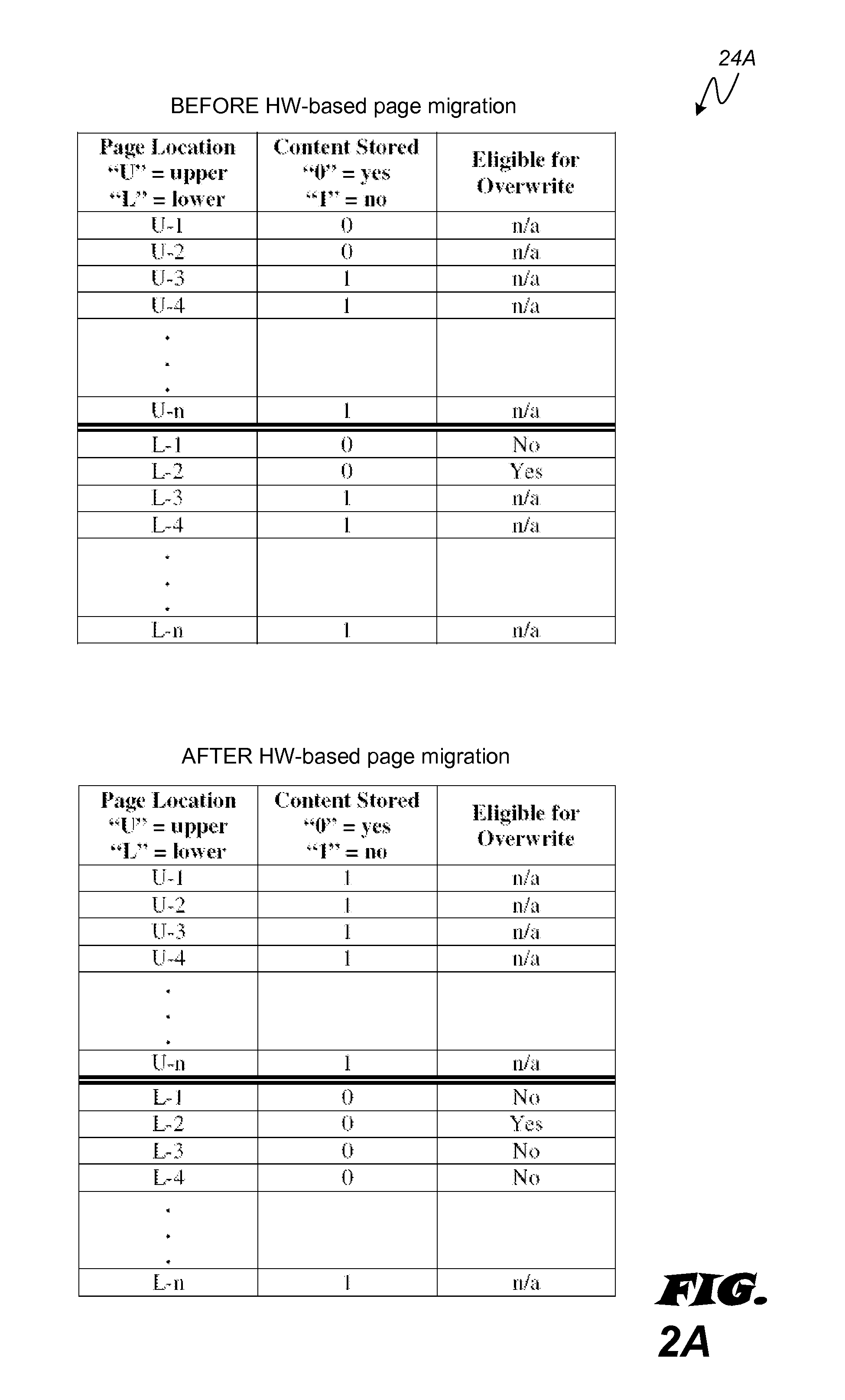
Embodiment Construction

[0018]The word “exemplary” is used herein to mean “serving as an example, instance, or illustration.” Any aspect described herein as “exemplary” is not necessarily to be construed as exclusive, preferred or advantageous over other aspects.

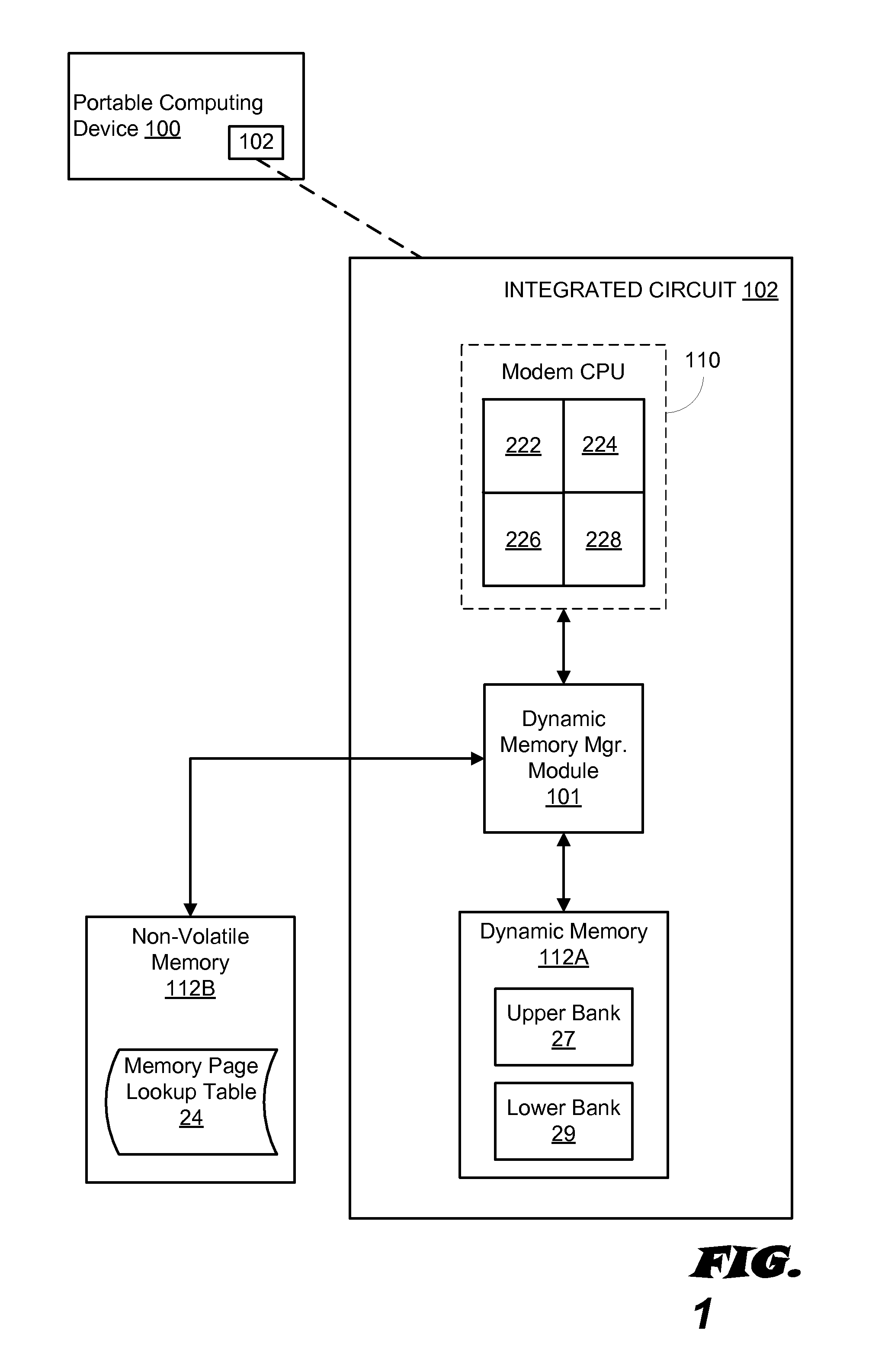
[0019]In this description, the term “portable computing device” (“PCD”) is used to describe any device operating on a limited capacity power supply, such as a battery. Although battery operated PCDs have been in use for decades, technological advances in rechargeable batteries coupled with the advent of third generation (“3G”) and fourth generation (“4G”) wireless technology have enabled numerous PCDs with multiple capabilities. Therefore, a PCD may be a cellular telephone, a satellite telephone, a pager, a PDA, a smartphone, a navigation device, a smartbook or reader, a media player, a combination of the aforementioned devices, a laptop computer with a wireless connection, among others.

[0020]In this description, the term “application” may also inc...


PUM


Abstract

Various embodiments of methods and systems for hardware (“HW”) based dynamic memory management in a portable computing device (“PCD”) are disclosed. One exemplary method includes generating a lookup table (“LUT”) to track each memory page located across multiple portions of a volatile memory. The records in the LUT are updated to keep track of data locations. When the PCD enters a sleep state to conserve energy, the LUT may be queried to determine which specific memory pages in a first portion of volatile memory (e.g., an upper bank) contain data content and which pages in a second portion of volatile memory (e.g., a lower bank) are available for receipt of content. Based on the query, the location of the data in the memory pages of the upper bank is known and can be quickly migrated to memory pages in the lower bank which are identified for receipt of the data.

Description

DESCRIPTION OF THE RELATED ART[0001]Portable computing devices (“PCDs”) are becoming necessities for people on personal and professional levels. These devices may include cellular telephones, portable digital assistants (“PDAs”), portable game consoles, palmtop computers, and other portable electronic devices. Because PCDs rely on a limited capacity power supply, such as a battery, conservation of the power supply is closely related to the overall quality of service (“QoS”) experienced by a user. That is, efficient use of the power resources in a PCD can reduce the frequency at which the user must recharge the battery.[0002]Most users don't use their PCD constantly and so it is common for a PCD to remain in an idle, sleep or standby mode for extended periods of time. Importantly, during these sleep periods, even though in an “idle” mode, the PCD is still consuming power in the form of a sleep current. The sleep current of a PCD is the sum of the leakage rates associated with various...

Claims


Application Information

Patent Timeline
Patent Type & Authority Patents(United States)
IPC IPC(8): G06F1/32G06F12/02
CPCG06F1/3225G06F1/3275G06F12/023Y02B60/32Y02B60/1228Y02D10/00Y02D30/50
Inventor LO, HAW-JINGTAHA, ALICHUN, DEXTER T.
Owner QUALCOMM INC
Why Eureka
Try Eureka