Check patentability & draft patents in minutes with Patsnap Eureka AI!

Air to refrigerant heat exchanger with phase change material

a phase change material and heat exchanger technology, applied in indirect heat exchangers, heating types, lighting and heating apparatuses, etc., can solve the problem that the fuel-powered engine no longer operates when the fuel-powered engine is not in operation, and achieve the effect of maximizing the effect and efficiency of the engin

Active Publication Date: 2015-08-18
HANON SYST
View PDF38 Cites 1 Cited by
  • Summary
  • Abstract
  • Description
  • Claims
  • Application Information

AI Technical Summary

Benefits of technology

The thermal energy exchanger effectively maintains passenger compartment comfort by absorbing and releasing thermal energy using phase change materials, ensuring efficient air conditioning even when the fuel-powered engine is not in operation, thereby improving HVAC system effectiveness and efficiency.

Problems solved by technology

However, in recent years, vehicles having improved fuel economy over the fuel-powered engine and other vehicles are quickly becoming more popular as a cost of traditional fuel increases.
Although the technologies improve fuel economy, accessories powered by the fuel-powered engine no longer operate when the fuel-powered engine is not in operation.

Method used


Image

  • Air to refrigerant heat exchanger with phase change material
  • Air to refrigerant heat exchanger with phase change material
  • Air to refrigerant heat exchanger with phase change material

Examples


Embodiment Construction

[0027]The following detailed description and appended drawings describe and illustrate various exemplary embodiments of the invention. The description and drawings serve to enable one skilled in the art to make and use the invention, and are not intended to limit the scope of the invention in any manner.

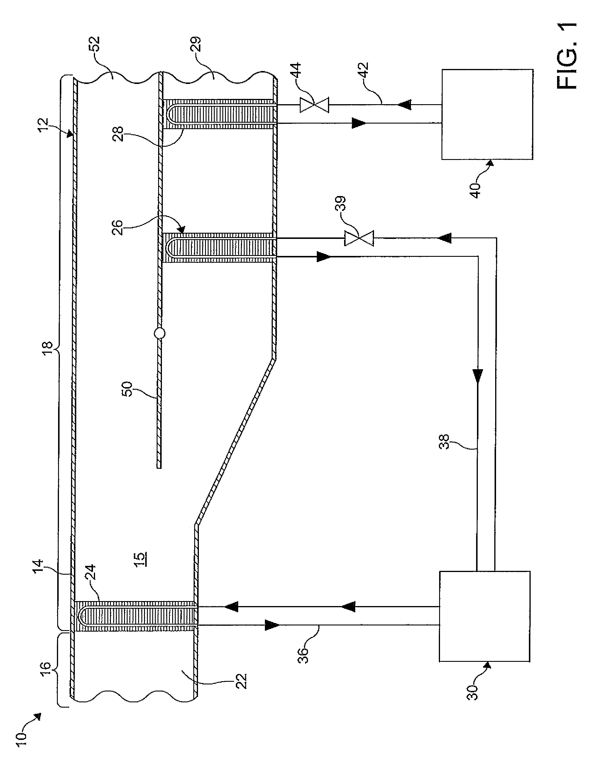
[0028]FIG. 1 shows a heating, ventilating, and air conditioning (HVAC) system 10 according to an embodiment of the invention. The HVAC system 10 typically provides heating, ventilation, and air conditioning for a passenger compartment of a vehicle (not shown). The HVAC system 10 includes a control module 12 to control at least a temperature of the passenger compartment.

[0029]The module 12 illustrated includes a hollow main housing 14 with an air flow conduit 15 formed therein. The housing 14 includes an inlet section 16, a mixing and conditioning section 18, and an outlet and distribution section (not shown). In the embodiment shown, an air inlet 22 is formed in the inlet section 16....


PUM


Abstract

A thermal energy heat exchanger for an air conditioning system includes a row of first tubes, a row of second tubes, and a row of third tubes. Inside, heat is exchanged between air, refrigerant, and phase change material, also known as PCM, cool storage material, cold storage material, and latent heat storage material. The first row of tubes carries refrigerant. A portion of the second row of tubes and a portion of the third row of tubes carry refrigerant. The remainder of the second and third rows of tubes carry phase change material. The phase change material can be associated with a phase change material manifold. Advantageously, the melting point of phase change material in the second tubes can be different from the melting point of the phase change material in the third tubes.

Description

FIELD OF THE INVENTION[0001]The invention relates to a climate control system for a vehicle and more particularly to a heating, ventilating, and air conditioning system of a vehicle having a thermal energy exchanger disposed therein.BACKGROUND OF THE INVENTION[0002]A vehicle typically includes a climate control system which maintains a temperature within a passenger compartment of the vehicle at a comfortable level by providing heating, cooling, and ventilation. Comfort is maintained in the passenger compartment by an integrated mechanism referred to in the art as a heating, ventilating and air conditioning (HVAC) system. The HVAC system conditions air flowing therethrough and distributes the conditioned air throughout the passenger compartment.[0003]Typically, a compressor of a refrigeration system provides a flow of a fluid having a desired temperature to an evaporator disposed in the HVAC system to condition the air. The compressor is generally driven by a fuel-powered engine of ...

Claims


Application Information

Patent Timeline
Patent Type & Authority Patents(United States)
IPC IPC(8): F28D20/02B60H1/00F24F5/00F28D20/00F28D1/053
CPCF28D1/05383B60H1/005B60H1/00328F28D20/026F24F5/0021F28D1/05391F28D20/02F28D2020/0008F28D2020/0013Y02E60/145Y02E60/147Y02E60/14
Inventor GOENKA, LAKHI, NANDLAL
Owner HANON SYST
Features
  • R&D
  • Intellectual Property
  • Life Sciences
  • Materials
  • Tech Scout
  • Unparalleled Data Quality
  • Higher Quality Content
  • 60% Fewer Hallucinations
Learn More