Image sensor

a technology of image sensor and image, applied in the field of image sensor, can solve the problems of reducing image quality, complicated blooming phenomenon, and dedicated circuit for providing shutter for avoiding, and achieve the effect of simple configuration and good image quality

Inactive Publication Date: 2015-08-18
SONY SEMICON SOLUTIONS CORP
View PDF42 Cites 3 Cited by
  • Summary
  • Abstract
  • Description
  • Claims
  • Application Information

AI Technical Summary

Benefits of technology

[0020]According to an aspect of the present invention, a good-quality image can be obtained with a simple configuration.

Problems solved by technology

When the blooming phenomenon occurs, a white zonal or white circular pattern appears in an image, which may degrade image quality.
In order to deal with various imaging modes, a process of cropping the angle of view or a thinning process corresponding to the respective imaging modes needs to be handled, and thus the dedicated circuit for providing a shutter for avoiding the blooming phenomenon becomes complicated and the circuit scale thereof increases.
Furthermore, this dedicated circuit is dedicated to a specific imaging mode, and the circuit needs to be modified or a circuit needs to be newly added when the imaging mode is modified or another imaging mode is added, so that it is difficult to respond to modification or addition of an imaging mode.
However, the circuit becomes complicated and the circuit scale thereof increases.
Also, in an address control device that manages shutter positions, the number of shutter positions required to be managed increases and complexity occurs, and as a result, the circuit scale of the address control device increases.
Also, in a case where an adjoining pixel is being exposed, an unnecessary charge is accumulated in the pixel, which degrades image quality.

Method used


Image

  • Image sensor
  • Image sensor
  • Image sensor

Examples


Embodiment Construction

[0039]Hereinafter, a specific embodiment to which the present invention is applied will be described in detail with reference to the drawings.

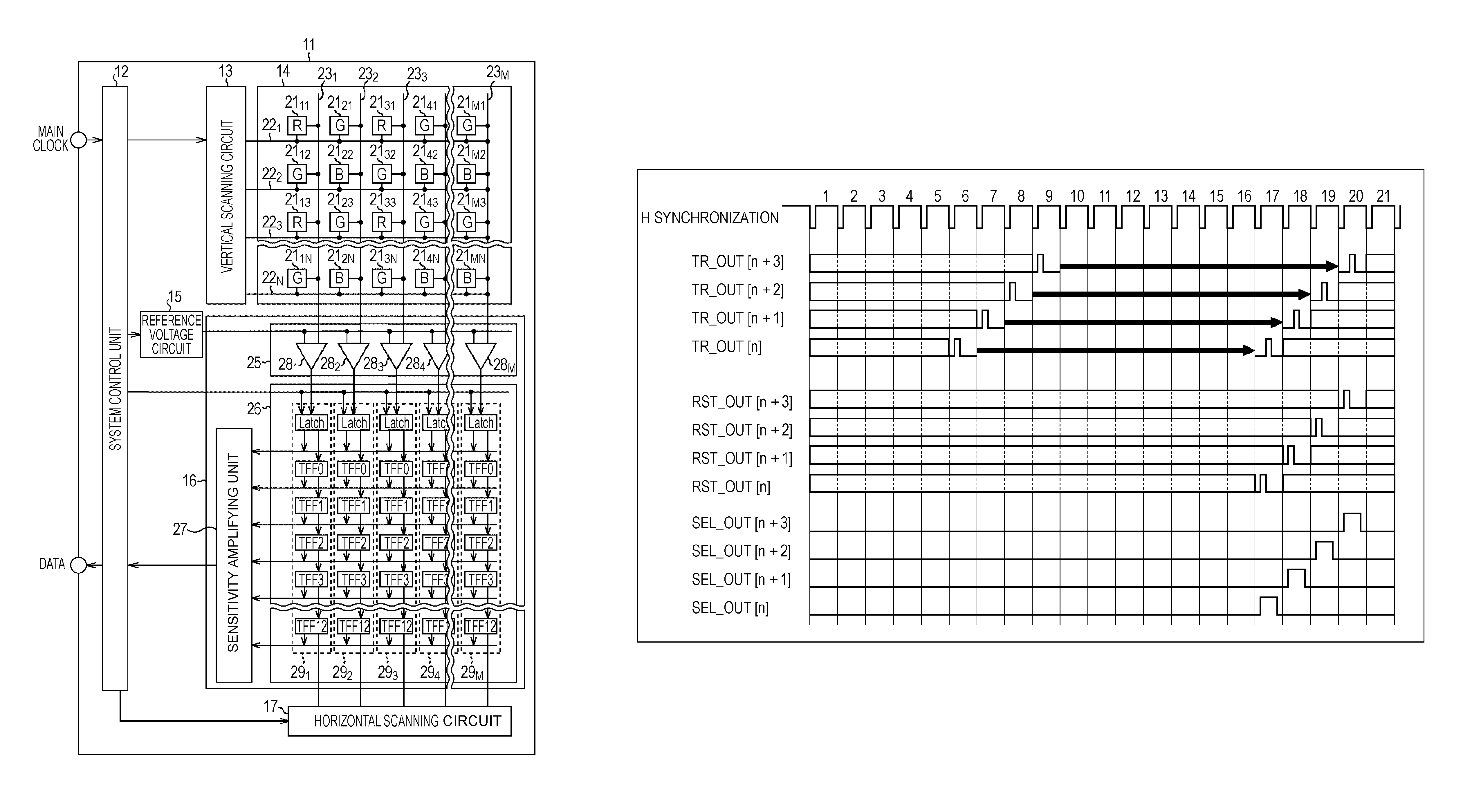
[0040]FIG. 1 is a block diagram illustrating a configuration example of an embodiment of a CMOS sensor to which the present invention is applied.

[0041]In FIG. 1, a CMOS sensor 11 is configured including a system control unit 12, a vertical scanning circuit 13, a pixel array 14, a reference voltage circuit 15, a column ADC (Analog to Digital Converter) 16, and a horizontal scanning circuit 17.

[0042]The system control unit 12 includes a logic control circuit, a PLL circuit (CLK frequency dividing), a timing control circuit, a communication interface, etc. A main clock is supplied to the system control unit 12 from an external circuit that is not illustrated, and the system control circuit 12 performs control of respective blocks constituting the CMOS sensor 11 and communication with the external circuit.

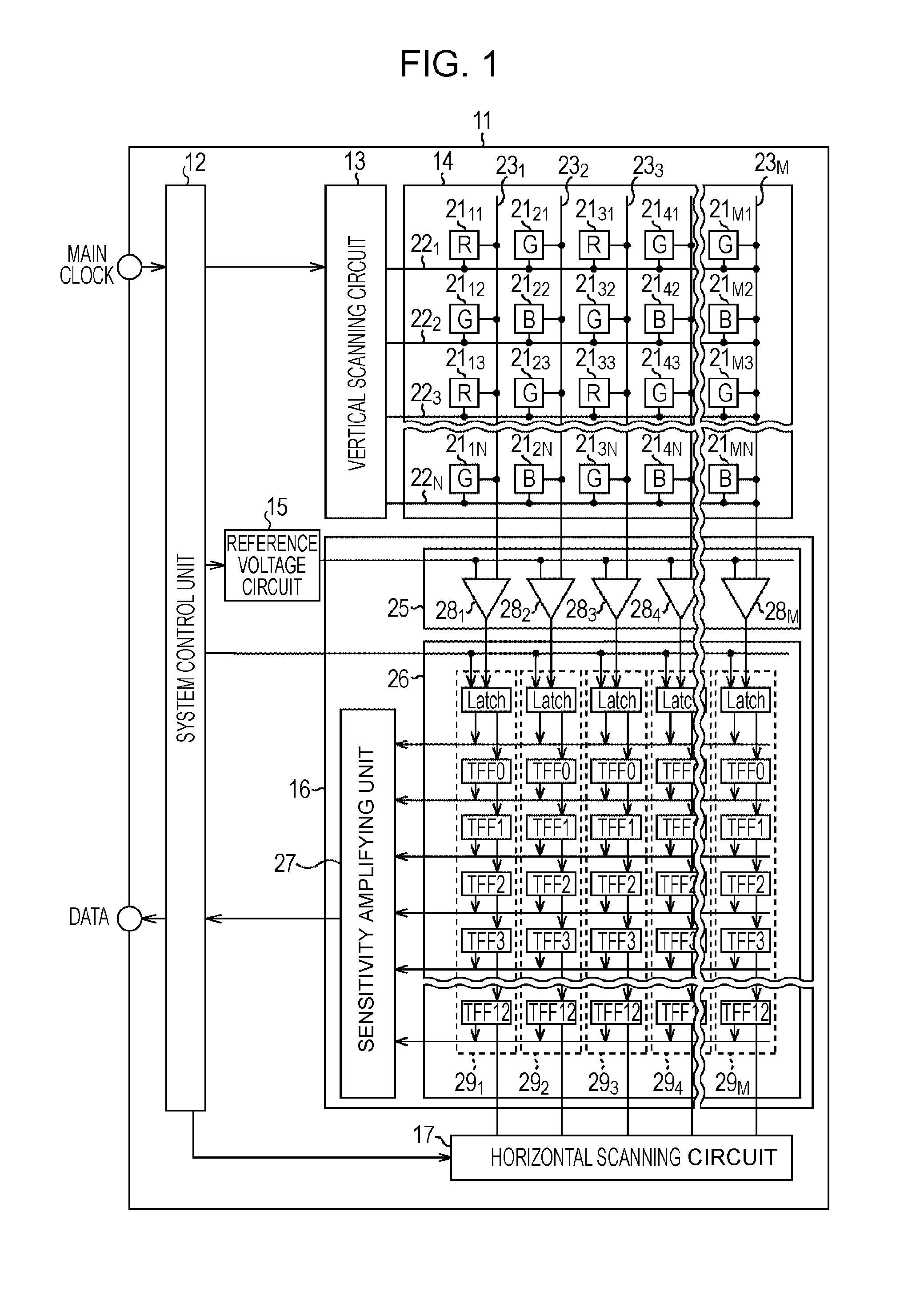
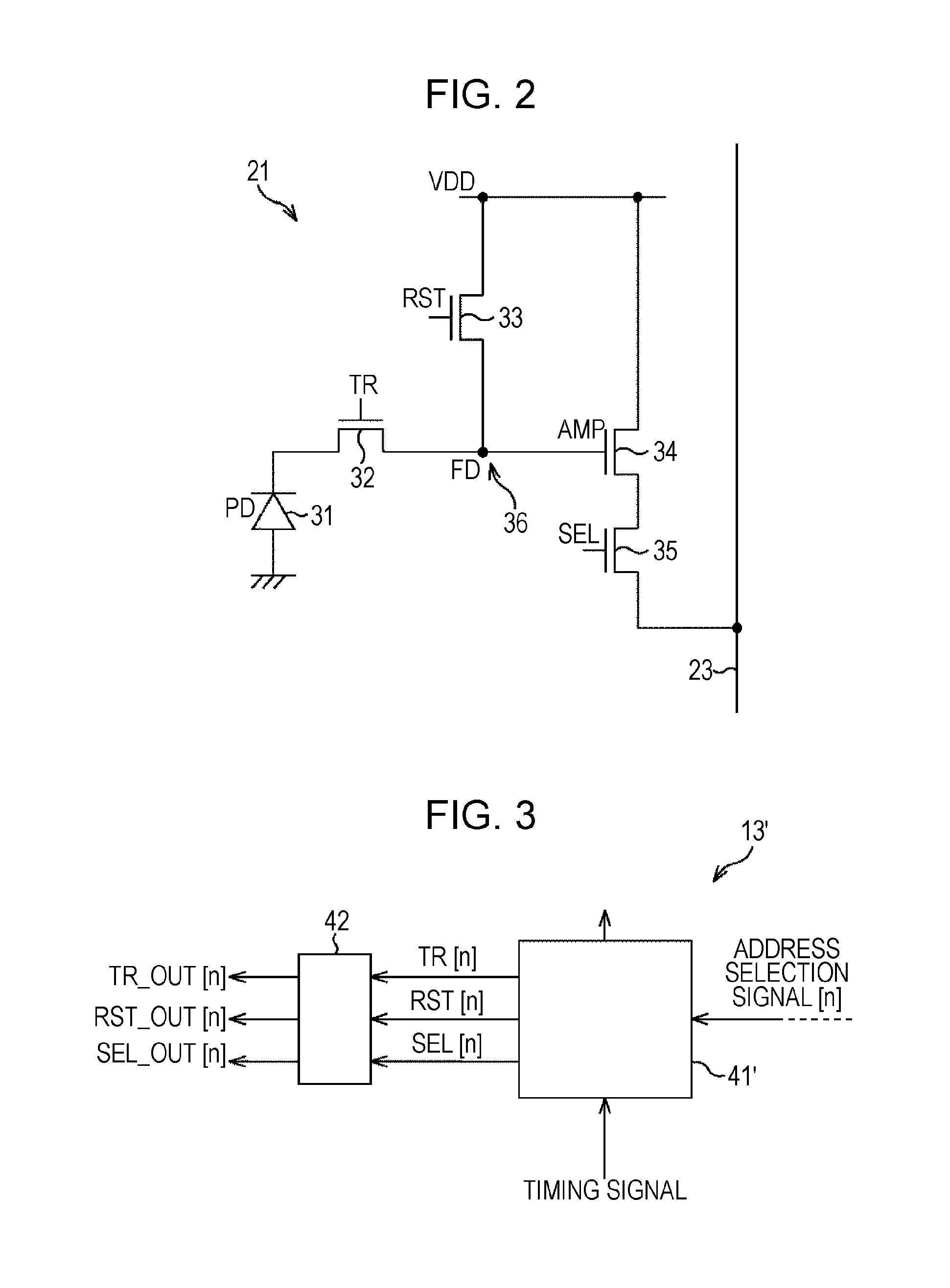
[0043]The vertical scanning circuit 13 seq...


PUM


Abstract

The present invention relates to an image sensor capable of obtaining a good-quality image with a simple configuration.A pixel accumulates a charge by performing photoelectric conversion on incident light, and outputs a pixel signal corresponding to the charge. A vertical scanning circuit controls the pixel to cause the pixel to perform a shutter process of discharging an unnecessary charge accumulated in the pixel, a charge accumulation process of accumulating a charge generated through photoelectric conversion in a predetermined exposure time in the pixel, and a read process of outputting a pixel signal corresponding to the charge accumulated in the pixel in the charge accumulation process. Also, the control means causes the charge generated through photoelectric conversion in the pixel to be discharged in a non-accumulation period, which is a period other than a period when the shutter process is being performed, a period when the charge accumulation process is being performed, and a period when the read process is being performed. The present invention can be applied to a CMOS sensor, for example.

Description

TECHNICAL FIELD[0001]The present invention relates to image sensors, and specifically relates to an image sensor capable of obtaining a good-quality image with a simple configuration.BACKGROUND ART[0002]Generally, in a CMOS (complementary metal oxide semiconductor) sensor, a plurality of pixels having photodiodes are arranged in a matrix pattern, and pixel signals corresponding to charges generated through photoelectric conversion performed by the photodiodes are output from the respective pixels.[0003]Also, the respective pixels of the CMOS sensor have transistors for controlling the output of pixel signals, and pixel signals are output in units of lines (rows) or in units of pixels in response to control signals that specify addresses of rows and columns.[0004]For example, each pixel is configured including four transistors: a transfer transistor; a reset transistor; an amplifying transistor; and a selection transistor. Also, a node connecting the transfer transistor, the reset tr...

Claims


Application Information

Patent Timeline
Patent Type & Authority Patents(United States)
IPC IPC(8): H01L27/146H04N5/376H04N5/345H04N5/353H04N5/3745H04N5/374H04N5/359H04N5/335H04N5/369
CPCH01L27/14654H01L27/14641H04N5/345H04N5/353H04N5/3594H04N5/376H04N5/3742H04N5/37457H04N25/44H04N25/53H04N25/623H04N25/767H04N25/778H04N25/74
Inventor TAKAMIYA, KENICHIKOSEKI, KEN
Owner SONY SEMICON SOLUTIONS CORP
Why Eureka
Try Eureka