Drive roll assembly

a technology of drive roll and feeder, which is applied in the direction of soldering apparatus, manufacturing tools,auxillary welding devices, etc., can solve the problems of aluminum wire easily being damaged, aluminum wire can present some real challenges, and the machine setting that works well with steel wire may not be suitable,

Active Publication Date: 2015-08-25
LINCOLN GLOBAL INC
View PDF20 Cites 6 Cited by
  • Summary
  • Abstract
  • Description
  • Claims
  • Application Information

AI Technical Summary

Benefits of technology

[0010]In another aspect of the invention, a push-pull drive system for a welding wire feeder conveying associated electrically charged wire, is described which includes at least: a first wire feeding means positioned external to a welding wire gun, the first wire feeding means comprising: a generally rigid apertured first feed plate having one or more recesses; at least one first pair of drive rollers rotatably connected with respect to the first feed plate, wherein the drive rollers are spaced apart to propel the associated electrically charged wire, the first pair of drive rollers having a first pair of opposed rollers which matingly engage with each of the drive rollers; a first means for reducing rolling friction operatively positioned between each of the first rollers and the first feed plate, the first means for reducing rolling friction being coaxially positioned with the first rollers, and wherein the first means for reducing rolling friction is electrically non-conducting for substantially preventing the discharge of electrical energy between the first feed plate and the first rollers; and a second wire feeding means positioned within the welding wire gun, the second wire feeding means comprising: a second apertured welding wire feed plate positioned within the welding gun, one side of the second feed plate connected to a gun gooseneck; at least one second pair of drive rollers rotatably connected with respect to the second feed plate, wherein the second pair of drive rollers are spaced apart to propel the associated electrically charged wire, the second drive rollers having a pair of second opposed rollers which matingly engage with each of the second drive rollers; and a second means for reducing rolling friction operatively positioned between each of the second rollers and the second feed plate, the second means for reducing rolling friction being coaxially positioned with the second rollers, and wherein the second means for reducing rolling friction is electrically non-conducting for substantially preventing the discharge of electrical energy between the second feed plate and the second roller.
[0015]In yet another aspect of the invention, a spool gun drive system for a welding wire feeder conveying associated electrically charged wire, is described which includes at least: a wire feeding means positioned within the welding wire gun, the wire feeding means comprising: an apertured welding wire feed plate positioned within the welding gun, one side of the feed plate connected to a gun gooseneck; at least one pair of drive rollers rotatably connected with respect to the feed plate, wherein the pair of drive rollers are spaced apart to propel the associated electrically charged wire, the drive rollers having a pair of opposed rollers which matingly engage with each of the drive rollers; and a means for reducing rolling friction operatively positioned between each of said rollers and the feed plate, the means for reducing rolling friction being coaxially positioned with the rollers, and wherein the means for reducing rolling friction is electrically non-conducting for substantially preventing the discharge of electrical energy between the feed plate and the roller.

Problems solved by technology

However, aluminum can present some real challenges.
Equipment must be adapted specifically to handle the softer aluminum wire and machine settings that work well with steel wire may not be appropriate.
In fact, aluminum wire can easily be damaged by equipment set up for steel wire.

Method used


Image

  • Drive roll assembly
  • Drive roll assembly
  • Drive roll assembly

Examples


Embodiment Construction

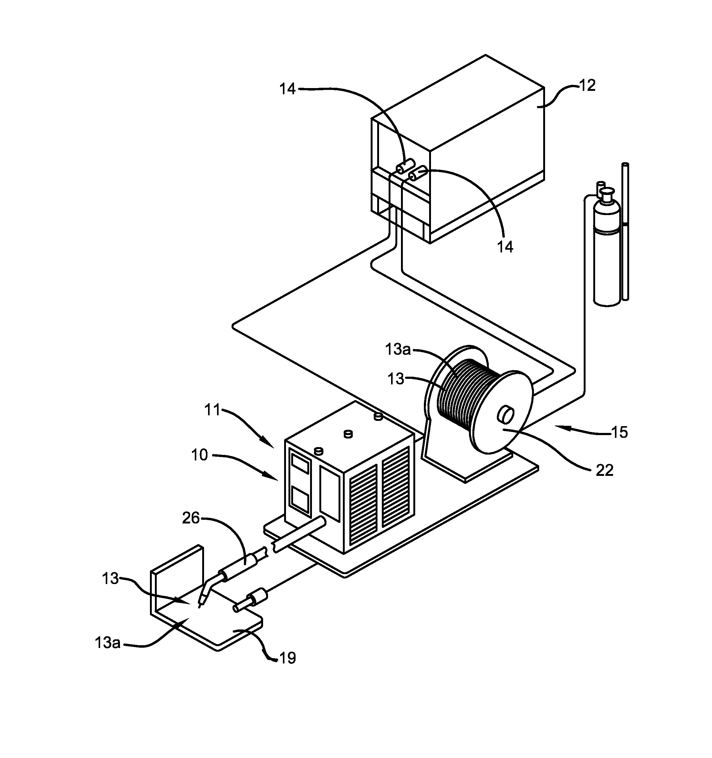
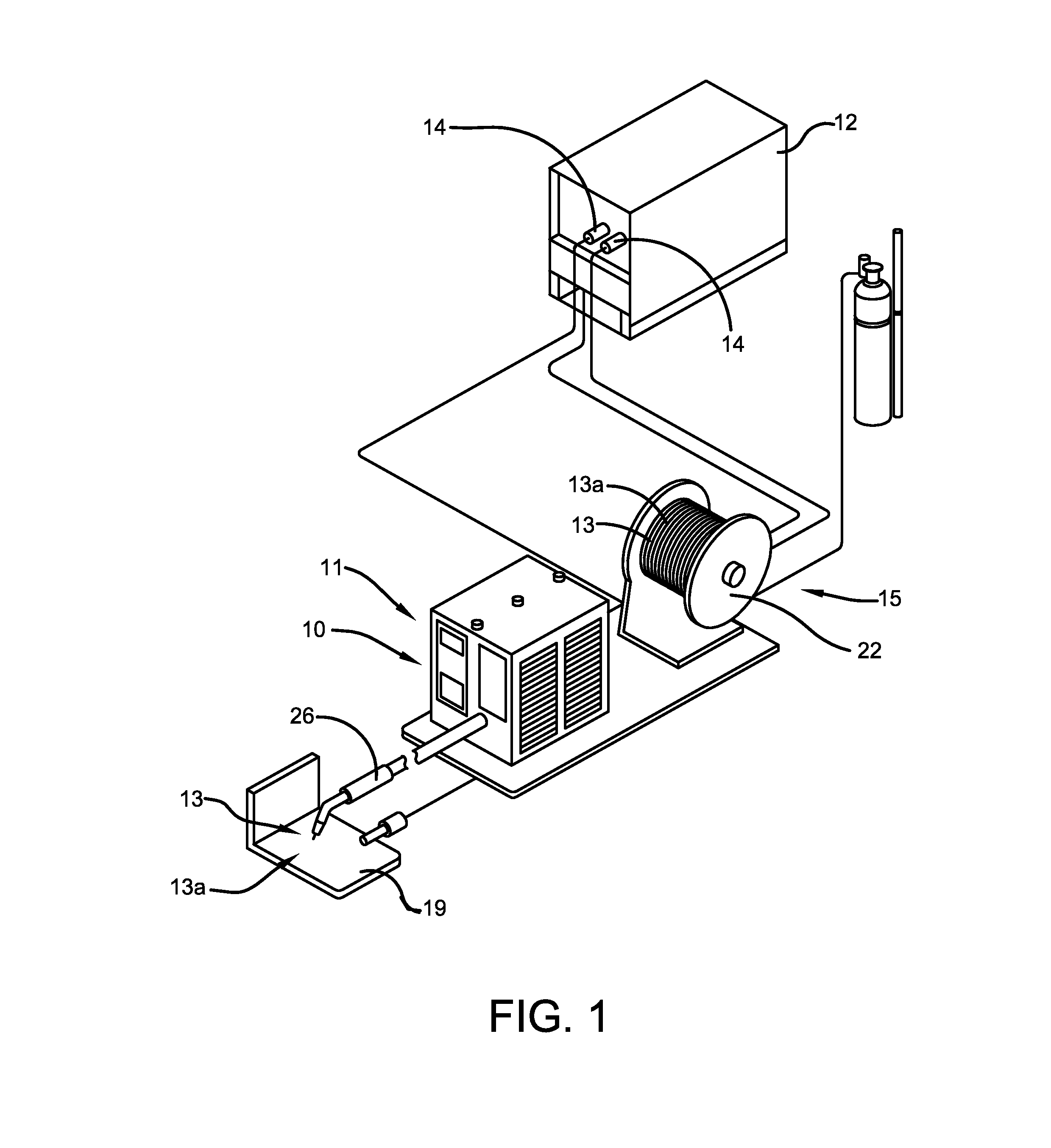
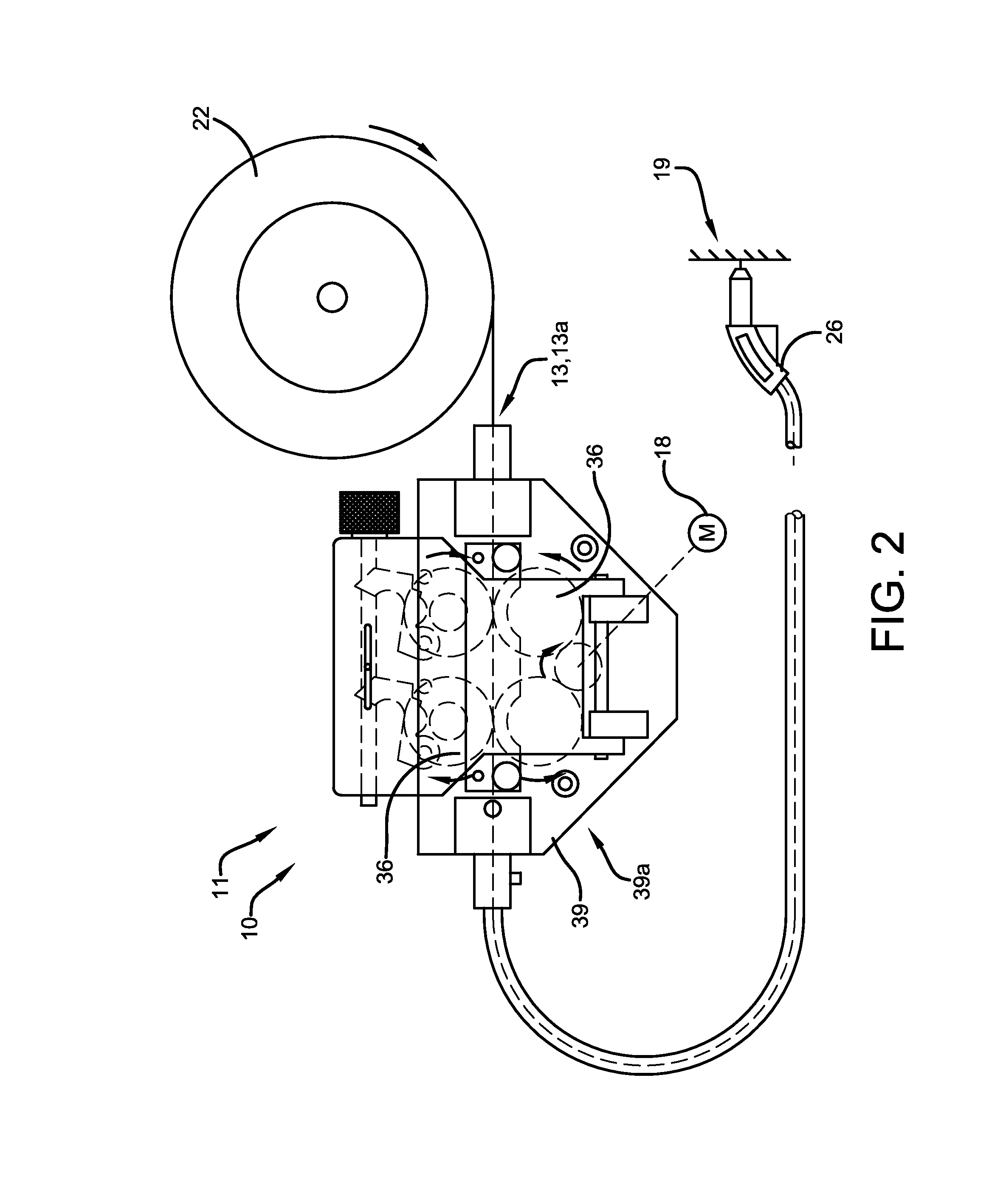
[0027]Referring now to the drawings wherein the showings are for purposes of illustrating embodiments of the invention only and not for purposes of limiting the same, FIG. 1 shows a wire feeder depicted generally at 10. The wire feeder 10 comprises a device for conveying wire 13 from a feed source 15, i.e. wire supply 15, for use in a particular application. For illustrative purposes, the wire feeder 10 will be described in the context of arc welding. However, other applications will become apparent to those skilled in the art, all of which should be construed as falling within the scope of coverage of the embodiments of the subject invention. In one embodiment, wire 13 may comprise a welding electrode 13a, also referred to herein as welding wire 13a, and wire feeder 10 may comprise welding wire feeder 11. Wire 13, 13a may be drawn continuously from a reel 22, box or drum, and delivered to a work piece 19, which in the current embodiment is a weldment. Accordingly, the wire feeder 1...


PUM

PropertyMeasurementUnit
tensionaaaaaaaaaa
lengthaaaaaaaaaa
poweraaaaaaaaaa

Abstract

A wire feeder includes a wire feeder housing that may enclose one or more drive rollers rotatably connected with respect to the wire feeder housing for engaging welding wire. The one or more drive rollers may be adjustable and adapted to drive the welding wire to a welding gun connected to the wire feeder. A drive motor is incorporated for delivering power for rotating the one or more drive rollers. Friction reducing devices, such as bearings, may be utilized and positioned between one or more driver rollers and the housing, where the bearings are electrically non-conducting for preventing the discharge of electrical energy across the bearing surfaces.

Description

CROSS-REFERENCE TO RELATED APPLICATIONS[0001]This application is a continuation-in-part of and claims priority to U.S. patent application Ser. No. 12 / 610,724 filed 2 Nov. 2009, the contents of which are fully incorporated by reference.TECHNICAL FIELD[0002]The present invention pertains to welding wire feeders, and more particularly, to welding wire feeders having electrically isolated components.BACKGROUND OF THE INVENTION[0003]Wire feeders, like those used in arc welding applications, convey wire from a continuous feed source to a weld torch. In many instances, the wire is fed from a reel or drum at a rate determined by the operating parameters of the power source. Accordingly, the wire feeder includes a drive motor that delivers the wire at various feed rates. Typically pinch rollers are used to grip the wire pushing, or in certain cases pulling, it toward the work piece. To facilitate smooth operation, bearings may be included that allow the pinch rollers to rotate with reduced f...

Claims


Application Information

Patent Timeline
Patent Type & Authority Patents(United States)
IPC IPC(8): B23K9/12B23K9/133B23K37/02
CPCB23K37/0247B23K9/1336
Inventor ENYEDY, EDWARD A.
Owner LINCOLN GLOBAL INC
Why Eureka
Try Eureka