Brake system for vehicle including continuously variable belt transmission

a technology of transmission belt and brake system, which is applied in mechanical equipment, transportation and packaging, and gearing, etc., can solve the problems of brake fade or vapor lock, and achieve the effect of reducing the rotary speed of the cv

Active Publication Date: 2015-08-25
KANZAKI KOKYUKOKI MFG
View PDF5 Cites 27 Cited by
  • Summary
  • Abstract
  • Description
  • Claims
  • Application Information

AI Technical Summary

Benefits of technology

[0007]An object of the invention is to provide a brake system for a vehicle equipped with a CVT so as to effectively reduce a rotary speed of a CVT output shaft drivingly connected to an axle and drive wheels, thereby preventing the vehicle descending a slope while the CVT functioning as the clutch-disengagement action from being unexpectedly accelerated.
[0008]To achieve the object, a brake system is provided, for a vehicle equipped with a CVT having a CVT input shaft and a CVT output shaft. The CVT functions as a clutch-disengagement action for isolating rotation of the CVT output shaft from rotation of the CVT input shaft when a rotary speed of the CVT input shaft is reduced to a certain level. The vehicle is equipped with a prime mover driving the CVT input shaft so that an output rotary speed of the prime mover defines the rotary speed of the CVT input shaft. The vehicle is equipped with an accelerator manipulator for controlling the output rotary speed of the prime mover. The brake system is configured to cause a resistance against the rotation of the CVT output shaft according to an operation of the accelerator manipulator to reduce the output rotary speed of the prime mover so as to make the CVT function as the clutch-disengagement action.
[0009]Therefore, the brake system causing the resistance functions similar to an engine brake of a vehicle equipped with a gear transmission. The resistance caused by the brake system effectively reduces the rotary speed of the CVT output shaft drivingly connected to an axle and drive wheels of the vehicle so as to prevent the vehicle descending a slope, while the CVT functions as the clutch-disengagement action, from being unexpectedly accelerated. Further, therefore, the brake system advantageously reduces the need of repetitive manipulation for applying another manipulatable brake e.g., depression of a brake pedal for applying a drum brake provided on an axle of the vehicle, thereby ensuring a stable action of the manipulatable brake and prolonging a life of the manipulatable brake.

Problems solved by technology

However, when the vehicle descends a slope at an engine idling speed, an operator of the vehicle has to repeat depressing a brake pedal for braking the axle because the belt, the driven pulley and the CVT output shaft receive no power from the idling engine while the driver pulley functions as the clutch-disengagement action.
Such a repeat of braking may possibly cause a brake fade or a vapor lock.

Method used


Image

  • Brake system for vehicle including continuously variable belt transmission
  • Brake system for vehicle including continuously variable belt transmission
  • Brake system for vehicle including continuously variable belt transmission

Examples


Embodiment Construction

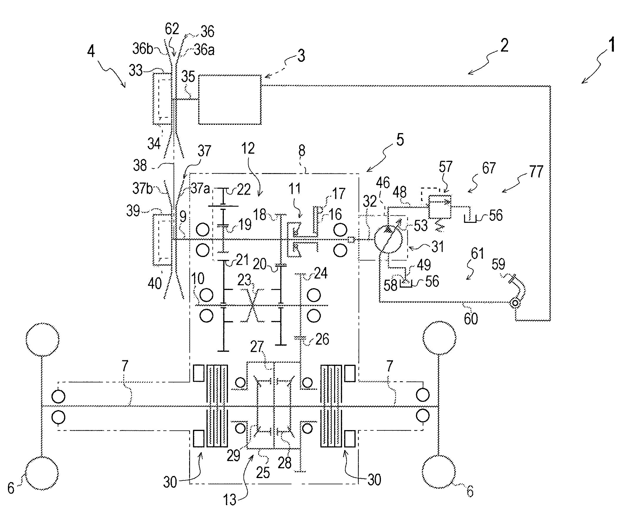
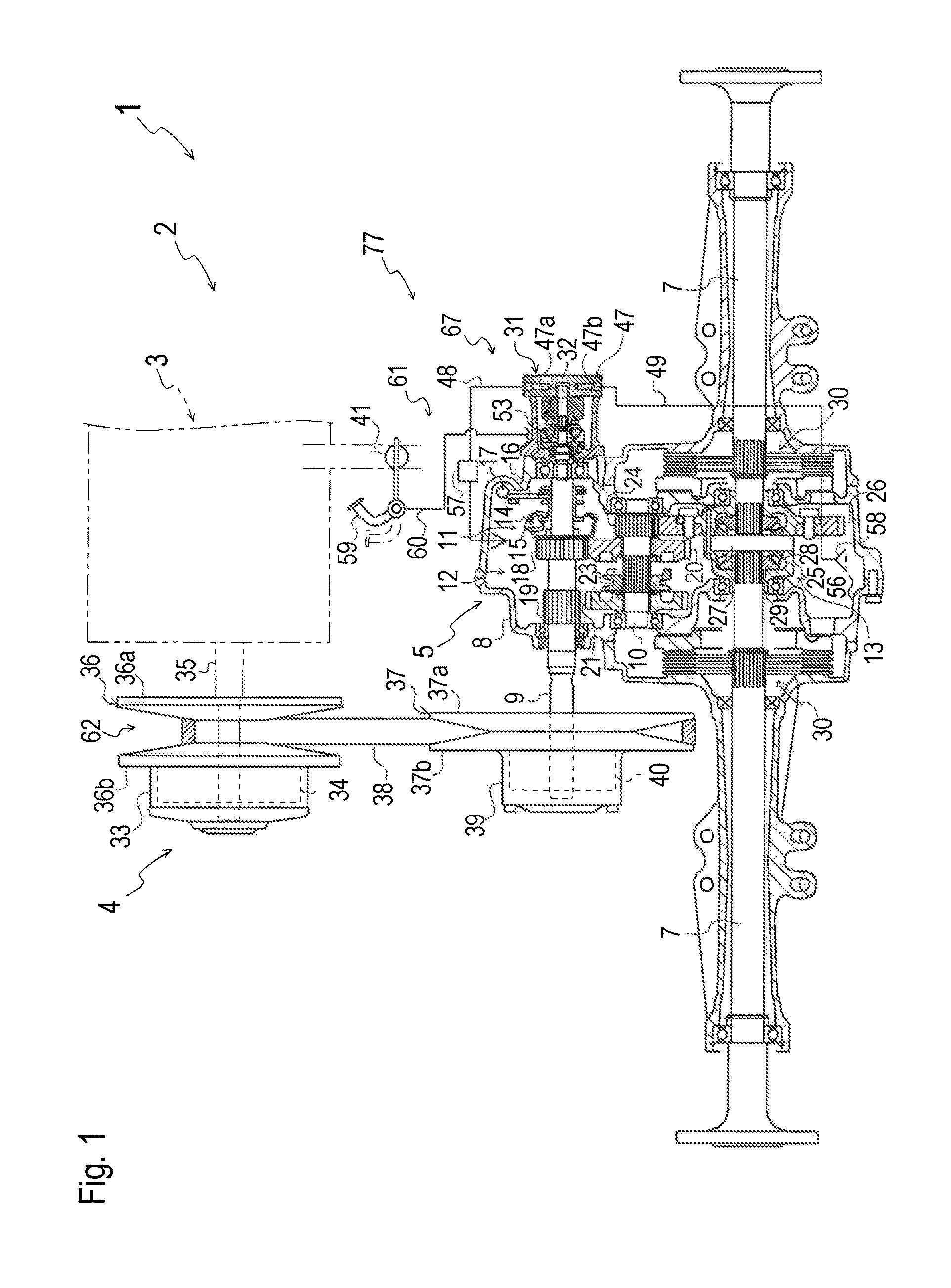
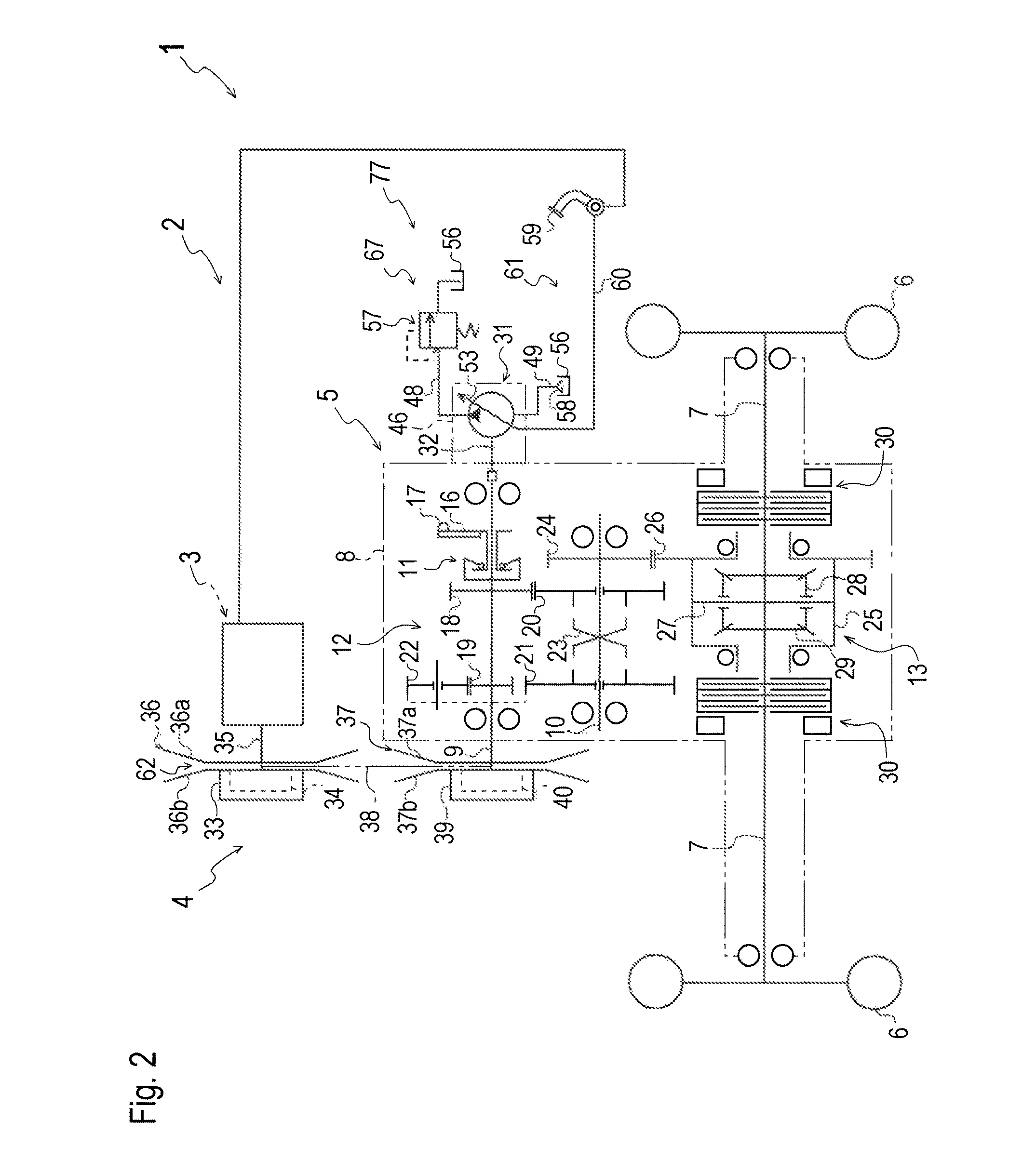
[0042]Referring to FIGS. 1 and 2, an axle driving power train 2 provided with a hydrodynamic brake system 77 for a vehicle 1, e.g., a golf car or golf cart, will be described on an assumption that axle driving power train 2 shown in FIGS. 1 and 2 is representative of axle driving power train 2 illustrated in FIGS. 6 to 9 as being provided with alternative brake systems 177, 177A and 277. Axle driving power train 2 includes an engine 3 serving as a prime mover, a CVT 4, and a transaxle 5 carrying right and left axles 7. Transaxle 5 receives power from engine 3 via CVT 4. Right and left drive wheels 6 are fixed on distal ends of respective axles 7.

[0043]Transaxle 5 includes a transaxle casing 8 supporting right and left axles 7. Transaxle casing 8 incorporates a governor 11, a reverser gear transmission 12 and a differential gear unit 13 differentially connecting right and left axles 7 to each other. An output shaft 9 of CVT 4 is journalled in transaxle casing 8 so as to serve as an i...


PUM


Abstract

A brake system is provided for a vehicle equipped with a continuously variable belt transmission (hereafter a “CVT”) having a CVT input shaft and a CVT output shaft. The CVT functions as a clutch-disengagement action for isolating rotation of the CVT output shaft from the CVT input shaft when a rotary speed of the CVT input shaft is reduced to a certain level. The vehicle is equipped with a prime mover driving the CVT input shaft so that an output rotary speed of the prime mover defines the rotary speed of the CVT input shaft. The vehicle includes an accelerator manipulator for controlling the output rotary speed of the prime mover. The brake system can cause a resistance against the rotation of the CVT output shaft using the accelerator manipulator to reduce the output rotary speed of the prime mover to make the CVT function as the clutch-disengagement action.

Description

BACKGROUND OF THE INVENTION[0001]1. Field of the Invention[0002]The present invention relates to a brake system for a vehicle equipped with a continuously variable belt transmission (hereinafter referred to as “CVT”).[0003]2. Related Art[0004]As disclosed by JP S48-44548 Y, a conventional CVT to be equipped on a vehicle such as a golf car or golf cart includes a driver pulley, a driven pulley and a belt interposed between the drive and driven pulleys. A pulley shaft of the driver pulley serves as an input shaft of the CVT, i.e., a CVT input shaft, to be drivingly connected to a prime mover such as an internal combustion engine arranged upstream of the CVT in a power train of the vehicle. A pulley shaft of the driven pulley serves as an output shaft of the CVT, i.e., a CVT output shaft, to be drivingly connected to an axle and drive wheels arranged downstream of the CVT in the power train of the vehicle.[0005]At least one of the driver and driven pulleys has a variable pitch diameter...

Claims


Application Information

Patent Timeline
Patent Type & Authority Patents(United States)
IPC IPC(8): B60W10/107B60W10/196B60W10/02B60T10/02B60T10/04B60W30/18F16H7/08F16H37/02
CPCB60W10/107B60T10/02B60T10/04B60W10/02B60W10/196B60W2030/18081B60W2540/10B60W2710/065F16H7/0827F16H37/021Y10T477/621Y10T477/6237
Inventor TSUKAMOTO, MICHIOIIDA, MASARU
Owner KANZAKI KOKYUKOKI MFG
Why Eureka
Try Eureka