Method for reducing write amplification on a data carrier with overlapping data tracks and device thereof

a data carrier and data track technology, applied in the field of data storage, can solve the problems of significant increase in the amount of data that must be read and written, unavoidable buffered data up to the next guard region, and the size of the write element is questionable, so as to reduce the amount of write amplification

Active Publication Date: 2015-08-25
INODYN NEWMEDIA
View PDF10 Cites 11 Cited by
  • Summary
  • Abstract
  • Description
  • Claims
  • Application Information

AI Technical Summary

Benefits of technology

[0015]Symmetrical bands may reduce write amplification, as the number of tracks that must be updated via read-modify-write typically is at least halved. A control unit, e.g., a hard disk controller, may maintain the number of taken or empty tracks on both sides of each symmetrical band substantially equal at every fill level of each symmetrical band.

Problems solved by technology

However, without new storage technologies, a reduction in the size of the write elements is questionable, as the magnetic field that can be generated is otherwise too small to adequately magnetize the individual bits on the disk surface.
With SMR, overlapping data tracks are grouped into bands, which are separated by inter-band gaps, also known as “guard bands,”“guard regions,” or “guard tracks.” Typically, to change the contents of a first track in an already populated band, it is necessary to read out and buffer all subsequent tracks of the band because after updating the data on that first track, rewriting the buffered data up to the next guard region is unavoidable as the wide write element will inevitably overwrite the data of each subsequent track.
Due to the sequential and overlapping structure of SMR, even a small change to the contents stored in a band can result in a significant increase in the amount of data that must be read and written, thus leading to significant delays.
These are the most expensive operations within an SMR storage system due to their significant write amplification, which negatively impacts performance.
Moreover, increasing file and data fragmentation can slow an SMR hard disk drive much more than it can a conventional hard-disk drive.
In the prior art SMR hard disk drives are deemed unsuitable as equal, universal substitutes for conventional hard disk drives.
If the required data throughput is permanently too high for the low write performance of an SMR hard disk drive, even a large buffer will run over, leading to a drastic drop in performance.
Furthermore, depending on the design, an additional and / or larger buffer, e.g., flash memory, can increase the production costs of an SMR hard disk drive.

Method used


Image

  • Method for reducing write amplification on a data carrier with overlapping data tracks and device thereof
  • Method for reducing write amplification on a data carrier with overlapping data tracks and device thereof
  • Method for reducing write amplification on a data carrier with overlapping data tracks and device thereof

Examples


first embodiment

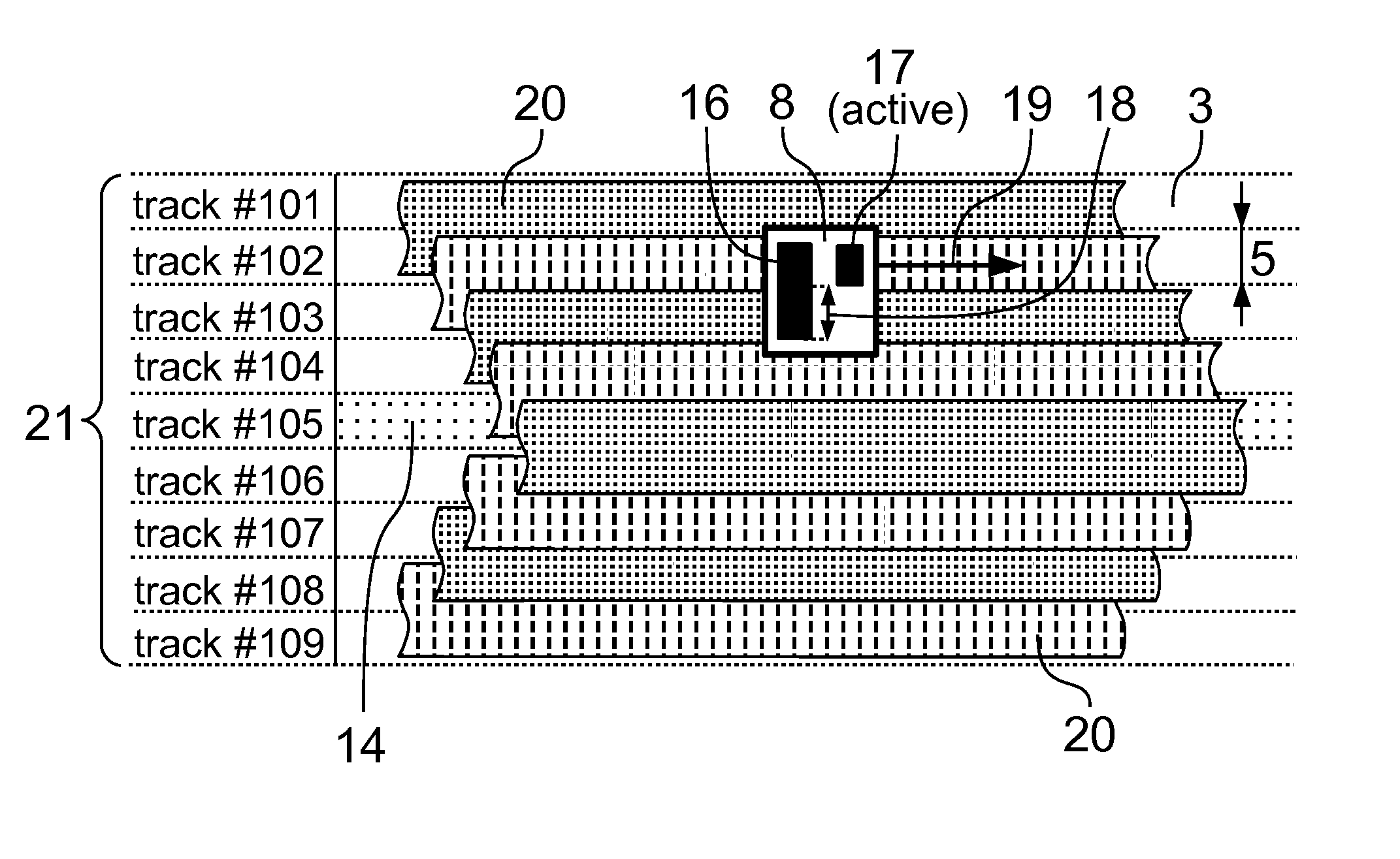
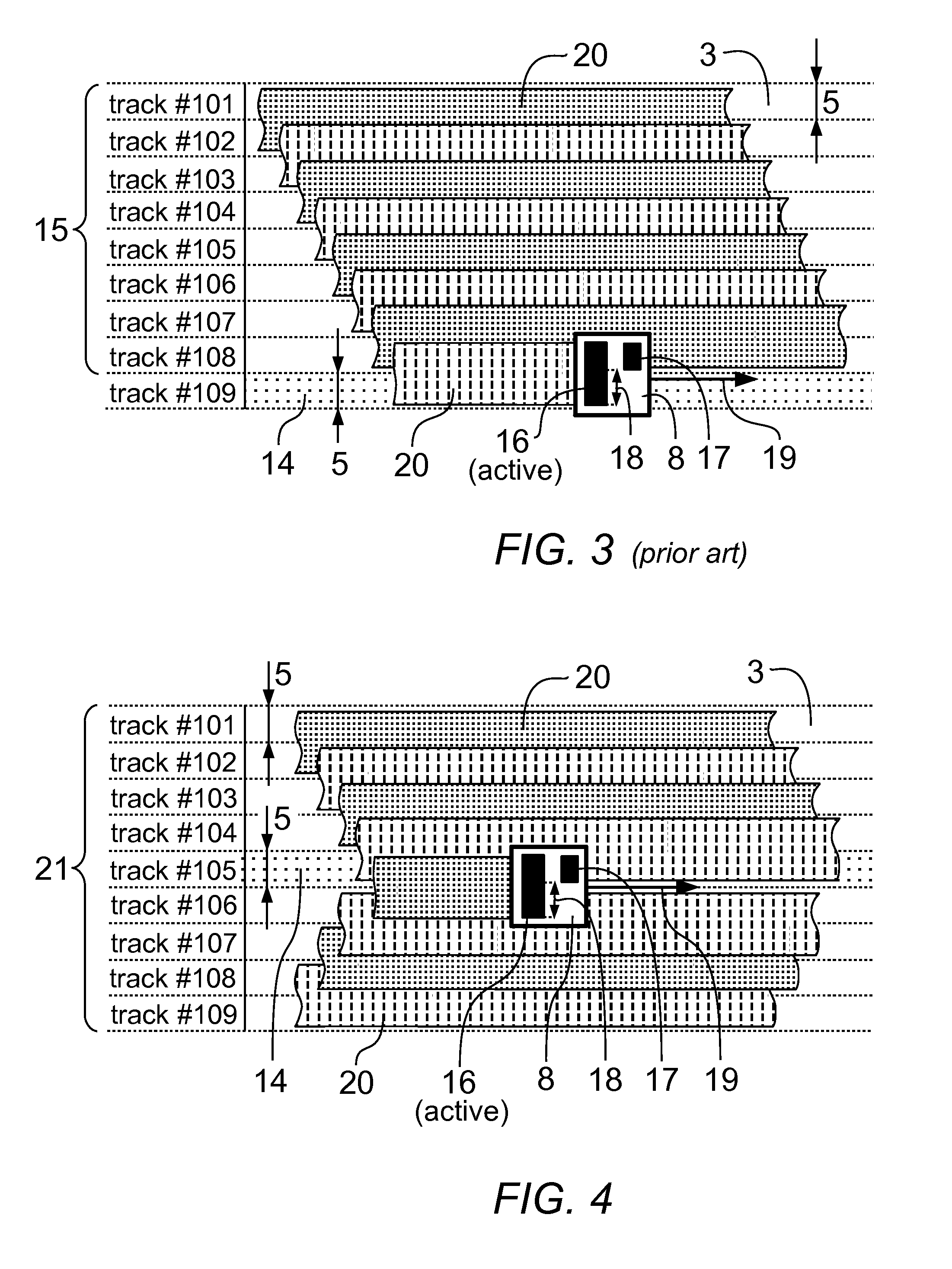
[0052]FIG. 4 and FIG. 5 show a first embodiment, introducing a novel band type for shingled magnetic recording, referred to herein as a symmetrical band 21. A symmetrical band 21 differs from a conventional band 15 in the position of the guard region 14, which is located in or near the middle of the band 21. For structural reasons, the guard region 14 in this case is defined as an integral part of the band 21. A plurality of symmetrical bands 21 can be arranged side-by-side without necessitating an additional gap exist between the band boundaries.

[0053]In the specific example shown in FIG. 4 the read / write head 8 and the number of tracks 3 per band 21 correspond to the previous example of a conventional band 15, that is, the write element 16 writes data tracks 20 that are twice as wide as the underlying track width 5, and the band 21 contains eight tracks 3 that can be used to store data. However, in this case, the guard track 14 is located on track #105 and, thus, in the middle of ...

second embodiment

[0060]The symmetrical overlaps of data tracks 20 within a band 21 may also be arranged in the opposite direction. In this case, the overlapping data tracks 20 may diverge in the middle of the band 22 or at a location near the middle, and the guard regions 14 may be located at the upper and lower band boundaries. This second embodiment is illustrated in FIG. 6. Here, the overlapping data tracks 20 diverge between tracks #104 and #105 and the guard tracks 14 are located at the band boundaries on track #100 and #109. In this context, the guard regions or guard tracks 14 are defined as separate instances and are not embedded within the band 22, as each guard region or guard track 14 may also be used by an adjacent band 22.

[0061]To fill the band 22 with data, overlapping data tracks 20 may be written by the wide write element 16 on both sides of the symmetrical band 22 from the inside out. This may result in overlaps in opposite radial directions, symmetrical to the center of the band 22...

third embodiment

[0062]FIG. 7 and FIG. 8 show a As in the previous examples, a read / write head 8 is used whose write element 16 writes data tracks 20 that are twice as wide as the track width 5. Tracks 3 are grouped into symmetrical bands 21, each comprising four usable tracks 3 and one guard track 14 at the center. In this example, a disk surface 2 incorporates 995 tracks, counted from track #000 to track #994, grouped into 199 bands.

[0063]For the sake of clarity and to keep the drawings manageable, each disk surface 2 in this embodiment has a very low track count. It is to be expressly noted that actual embodiments may have much larger track counts. Furthermore, it is pointed out that some parts, regions, or sections of the disk surface 2 may be used or reserved for other purposes. It should also be noted that the drawings represent only one disk surface 2. Further disk surfaces 2, if any, may be filled in the same manner.

[0064]The drawings illustrate how the tracks 3 of the SMR hard disk drive 1...


PUM

PropertyMeasurementUnit
widthaaaaaaaaaa
distanceaaaaaaaaaa
magnetic recording methodologyaaaaaaaaaa

Abstract

A novel symmetrical band is disclosed, which may be used in connection with shingled magnetic recording (SMR) in order to reduce write amplification (read-modify-write). Depending on the embodiment, overlapping data tracks diverge from, or converge to the center of each symmetrical band. Associated guard regions may be located at the center, or at the band boundaries, and are shared such that the excess width of a write element is caught by the guard regions from both sides. A symmetrical band may reduce the maximum write amplification by more than half. A hard disk controller may maintain the number of taken or empty tracks on both sides of each symmetrical band substantially equal at every fill level.

Description

CROSS-REFERENCE TO RELATED APPLICATION[0001]This application claims priority from German Patent Application DE 10 2014 003 205.1, filed Mar. 4, 2014, the entire disclosure of which is expressly incorporated herein by reference.TECHNICAL FIELD[0002]The present invention relates to the field of data storage and, in particular, to efficient write operations in conjunction with storage devices having overlapping data tracks, such as a hard disk drive, operating according to the shingled magnetic recording (SMR) methodology.BACKGROUND OF THE INVENTION[0003]Common hard disk drives are storage devices comprising disks whose data-carrying surfaces are coated with a magnetic layer. Typically, the disks are positioned atop one another on a disk stack (platters) and rotate around an axis, or spindle. To store data, each disk surface is organized in a plurality of circular, concentric tracks. Groups of concentric tracks placed atop each other in the disk stack are called cylinders. Read / write h...

Claims


Application Information

Patent Timeline
Patent Type & Authority Patents(United States)
IPC IPC(8): G11B5/09G11B20/12
CPCG11B20/1252G11B2020/1238G11B20/1217G06F3/0601G11B5/012G06F3/0619G06F11/16G11B20/18G11B20/1258G11B2020/1297G06F3/0673G06F3/064G06F3/0676G06F12/10G06F2212/1032G06F2212/152G06F2212/21G06F2212/657G06F2212/70G06F11/1469
Inventor PANTEL, LOTHAR
Owner INODYN NEWMEDIA
Why Eureka
Try Eureka