
Method for activating a porous layer surface

a technology of porous layer and activation method, which is applied in the direction of basic electric elements, semiconductor/solid-state device manufacturing, electrical equipment, etc., can solve the problems of poor selectivity toward the surface and film also being modified in its shap

Active Publication Date: 2015-08-25
INTERUNIVERSITAIR MICRO ELECTRONICS CENT (IMEC VZW) +1
View PDF12 Cites 5 Cited by
  • Summary
  • Abstract
  • Description
  • Claims
  • Application Information

AI Technical Summary

Benefits of technology

[0006]An object of various embodiments is to provide a method which permits to raise the reactivity of a porous dielectric material surface in such a way as to enable a subsequent sealing layer deposition without significantly increasing the k value of the porous dielectric layer.
[0017]The embodiments permit increasing the reactivity of the exposed surface of a porous dielectric layer while ensuring that the reactivity of the bulk of the porous dielectric layer is not significantly raised. This advantageously permits, for example, applying a sealing layer on the porous dielectric layer without or with very limited presence of the sealing layer below the exposed surface of the porous dielectric layer (inside the pores in the sub-surface region). This permits keeping the k-value of the porous dielectric layer substantially unchanged.

Problems solved by technology

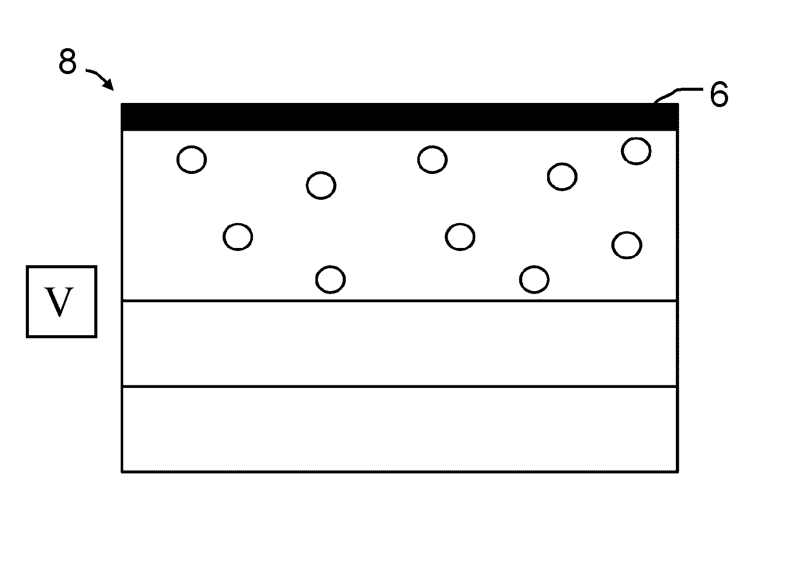
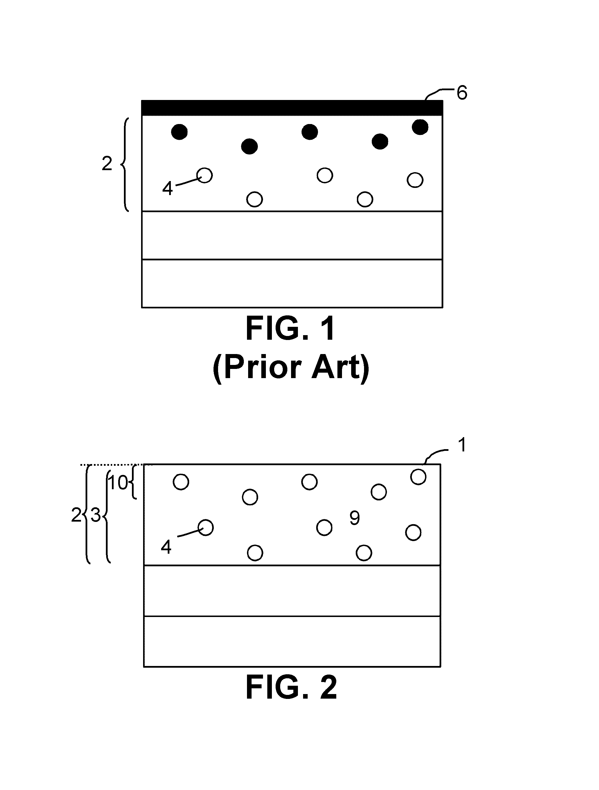
However, the used plasma technique showed poor selectivity toward the surface versus the bulk of the film (FIG. 1), meaning that the film was also modified in its bulk.

Method used


Image

  • Method for activating a porous layer surface
  • Method for activating a porous layer surface
  • Method for activating a porous layer surface

Examples


Embodiment Construction

[0026]The present invention will be described with respect to particular embodiments and with reference to certain drawings but the invention is not limited thereto. The drawings described are only schematic and are non-limiting. In the drawings, the size of some of the elements may be exaggerated and not drawn on scale for illustrative purposes. The dimensions and the relative dimensions do not correspond to actual reductions to practice of the invention.

[0027]The dimensions and the relative dimensions do not correspond to actual reductions to practice of the invention.

[0028]Furthermore, the terms “first”, “second”, “third” and the like, are used for distinguishing between similar elements and not necessarily for describing a sequence, either temporally, spatially, in ranking or in any other manner. It is to be understood that the terms so used are interchangeable under appropriate circumstances and that the embodiments of the invention described herein are capable of operation in ...


PUM

PropertyMeasurementUnit
boiling pointaaaaaaaaaa
contact angleaaaaaaaaaa
viscosityaaaaaaaaaa

Abstract

A method is provided for activating an exposed surface of a porous dielectric layer, the method comprising the steps of: filling with a first liquid at least the pores present in a part of the porous dielectric layer, the part comprising the exposed surface, removing the first liquid selectively from the surface, activating the exposed surface, and removing the first liquid from the bulk part of the porous dielectric layer.

Description

CROSS REFERENCE TO RELATED APPLICATION[0001]Any and all priority claims identified in the Application Data Sheet, or any correction thereto, are hereby incorporated by reference under 37 CFR 1.57. This application claims the benefit of EP 13197472.7 filed Dec. 16, 2013. The aforementioned application is incorporated by reference herein in its entirety, and is hereby expressly made a part of this specification.TECHNICAL FIELD OF THE INVENTION[0002]Surface treatments, more specifically protective surface treatments of porous dielectric materials prior to the sealing thereof, are provided. Also provided are devices obtained via such treatments and in particular to semiconductor devices.BACKGROUND OF THE INVENTION[0003]Low dielectric constant (low-k) materials are developed to meet the ever increasing challenges in the IC industry in terms of RC delay. These low-k materials are typically highly porous in order to decrease the k value. For porous dielectric films to meet the standards fo...

Claims


Application Information

Patent Timeline
Patent Type & Authority Patents(United States)
IPC IPC(8): H01L21/469H01L21/02
CPCH01L21/02359H01L21/02343H01L21/02126H01L21/02203H01L21/3105H01L21/76814H01L21/76826H01L21/76831
Inventor LE, QUOC TOANBAKLANOV, MIKHAILSUN, YITINGARMINI, SILVIA
Owner INTERUNIVERSITAIR MICRO ELECTRONICS CENT (IMEC VZW)
Learn More