Tunnelling instrument for subcutaneously placing an article, and method of use of said instrument

a technology of tunneling and articles, applied in the field of tunneling instruments, can solve the problems of increased risk of infection, reduced healing and incorporation rate of grafts, and tissue trauma inside the tunnel

Inactive Publication Date: 2015-09-01
PLASMED
View PDF6 Cites 2 Cited by
  • Summary
  • Abstract
  • Description
  • Claims
  • Application Information

AI Technical Summary

Benefits of technology

[0017]This particular tip construction has the advantage that the same tip can be used for the creation of a tunnel, whereby the diameter of the tunnel is approximately equal to the maximum diameter of the first portion, and the placement of an object within the tunnel, whereby the second portion is of a diameter which is equal to or less than the internal diameter of the object to be placed in the tunnel, such that the second portion can be inserted into the said object and the said object can be secured to the tip at the third portion.
[0026]This particular handle construction has the advantage of providing extra control and more accurate steering of a tunneller shaft, particularly when a long tunneller shaft is employed. This is because the handle can be attached at point along the length of the tunneller shaft. A further advantage is that there is no need to remove any end fittings, such as tips, from the tunneller shaft in order to attach the handle. This saves time, simplifies the tunnelling procedure and eliminates the risk of the end fittings being lost and subsequently replaced with an incorrect part.
[0032]This tunnelling instrument has the advantage that, due to the connection means, the appropriate tips are always readily available for quick attachment to the tunneller shaft. Thus, eliminating the risk of losing or incorrectly replacing the tips after they have been detached from the tunneller shaft. In addition, bidirectional tunnelling is permitted.
[0053]This tunnelling kit has the same advantages as the tunnelling instrument plus the additional advantage that the tips can be selected or mixed and matched to suit the particular requirements of the job.

Problems solved by technology

If the tunnel is undersized relative to the external diameter of the tubular graft, then trauma will be caused to the tissues inside the tunnel when the graft of consequently larger diameter is pulled through the smaller diameter tunnel.
If, on the other hand, the tunnel is oversized, then there will typically be gaps between the graft and the tissues inside the tunnel, and this potentially will continue along the whole length of the graft within the tunnel.
This can lead to various serious complications, including; a greatly reduced rate of healing and incorporation of the graft; the formation of seroma from the wall of the graft (sweating of the graft); an increased risk of infection; and painful swelling of the area.
The first type of the known instruments referred to above is clearly disadvantageous in having a fixed handle, in that this allows the article to be placed via one direction, namely pulled back through the tunnel.
Although the second type of known instrument is bi-directional, the handle, the tunnelling tip and the tubular article attachment tip require frequent changing, which is time consuming and thus undesirably lengthens the time of the operation.
Also, attaching the tubular article to the conventional bullet tip can cause the article to stand proud of the tip diameter, so that the act of pulling the article through the tunnel often results in the ends of the attached article to plough through the tunnel and cause trauma to the inside thereof.
This requires the operator subsequently to have to reattach the end of the tubular article to the attachment tip for placement in the next tunnel, again causing undesirable delay to the operation procedure.
This action consequently risks the twisting of the tubular article.
Such twisting is contradicted and can lead to serious problems.
Frequently in practice, the wrong sized bullet tip is used in producing the tunnel, as firstly it is not always easy visually to recognise small differences in tip diameters, and secondly the specifically sized tip may be missing from the surgical tray.
This leads to the production of incorrectly sized tunnels.
These demands complicate tip choice, as well as tunnelling directional choices.
It is also sometimes difficult to remove the hollow tube from the surgical tunnel once the tubular article is in place, and can easily cause more trauma to the tissues inside the tunnel on removal.
None of the three above mentioned known types of instrument can easily deal with the tunnelling of longer tubular grafts and catheters, because of the physical constraints of their designs and their inherent requirement for bullet tip changes and handle changes.
The rigid rod or tube type tunneller does not allow for the easy placement of a long continuous tubular device or catheter in more than one single tunnel, because it is often constrained by its rigidity, and furthermore the development of alternative operative techniques of tubular graft placement are restricted by these shortcomings in tunneller design.
Another problem is that all of the designs are mostly reusable metal instruments and as such require cleaning and resterilization prior to reuse.
This leads to more complicated directional choices in tunnelling technique and frequent changes in tunneller handle and the various sized tips with respect to the tunneller shaft.

Method used


Image

  • Tunnelling instrument for subcutaneously placing an article, and method of use of said instrument
  • Tunnelling instrument for subcutaneously placing an article, and method of use of said instrument
  • Tunnelling instrument for subcutaneously placing an article, and method of use of said instrument

Examples


Embodiment Construction

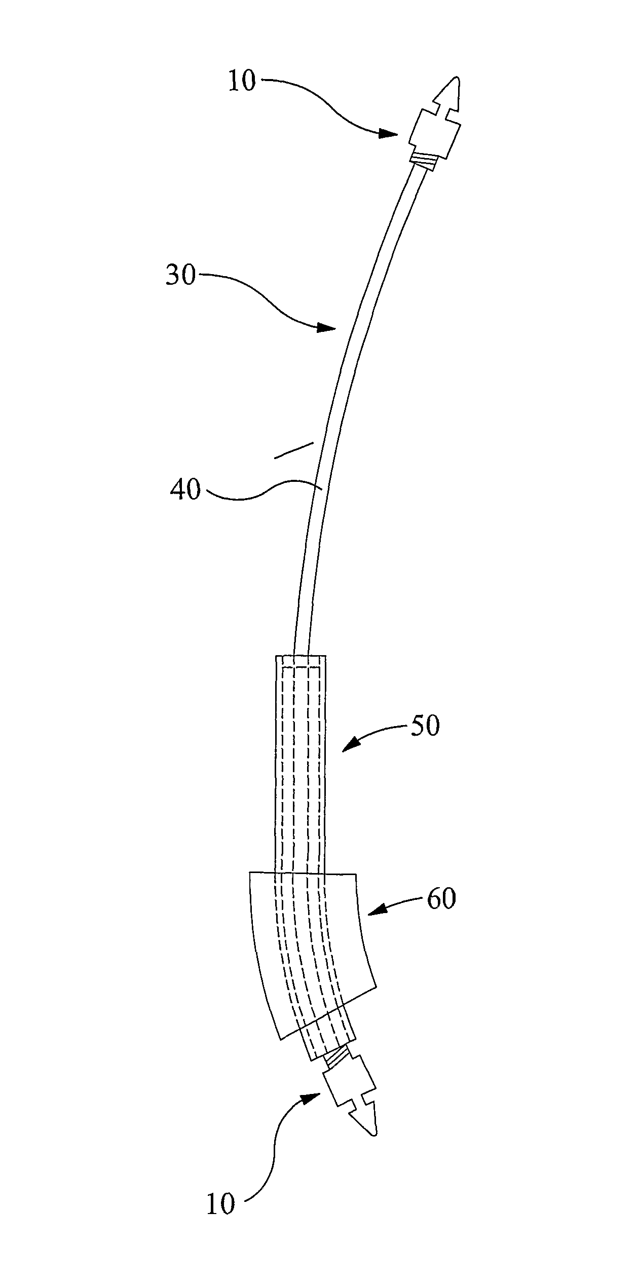
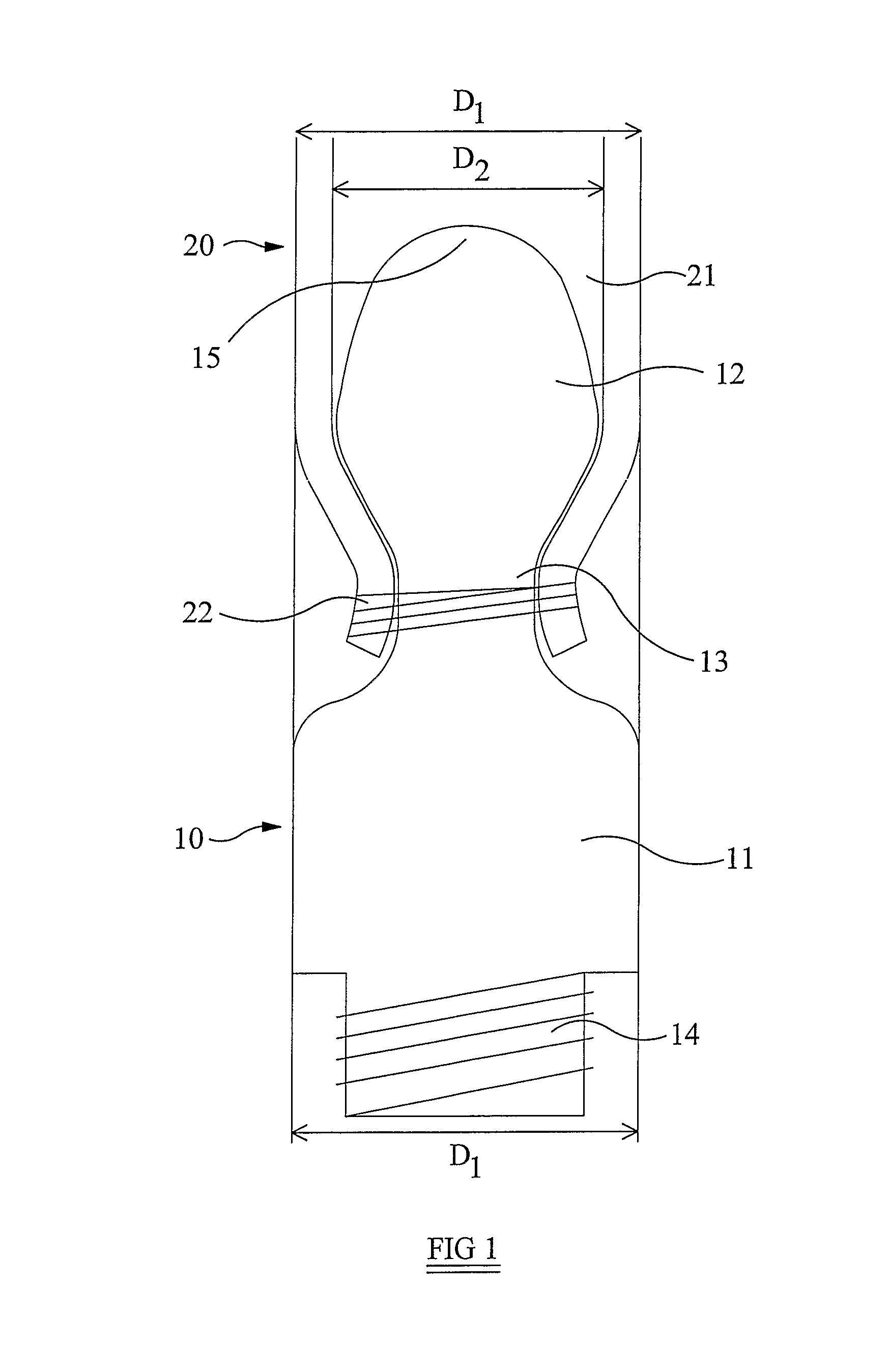
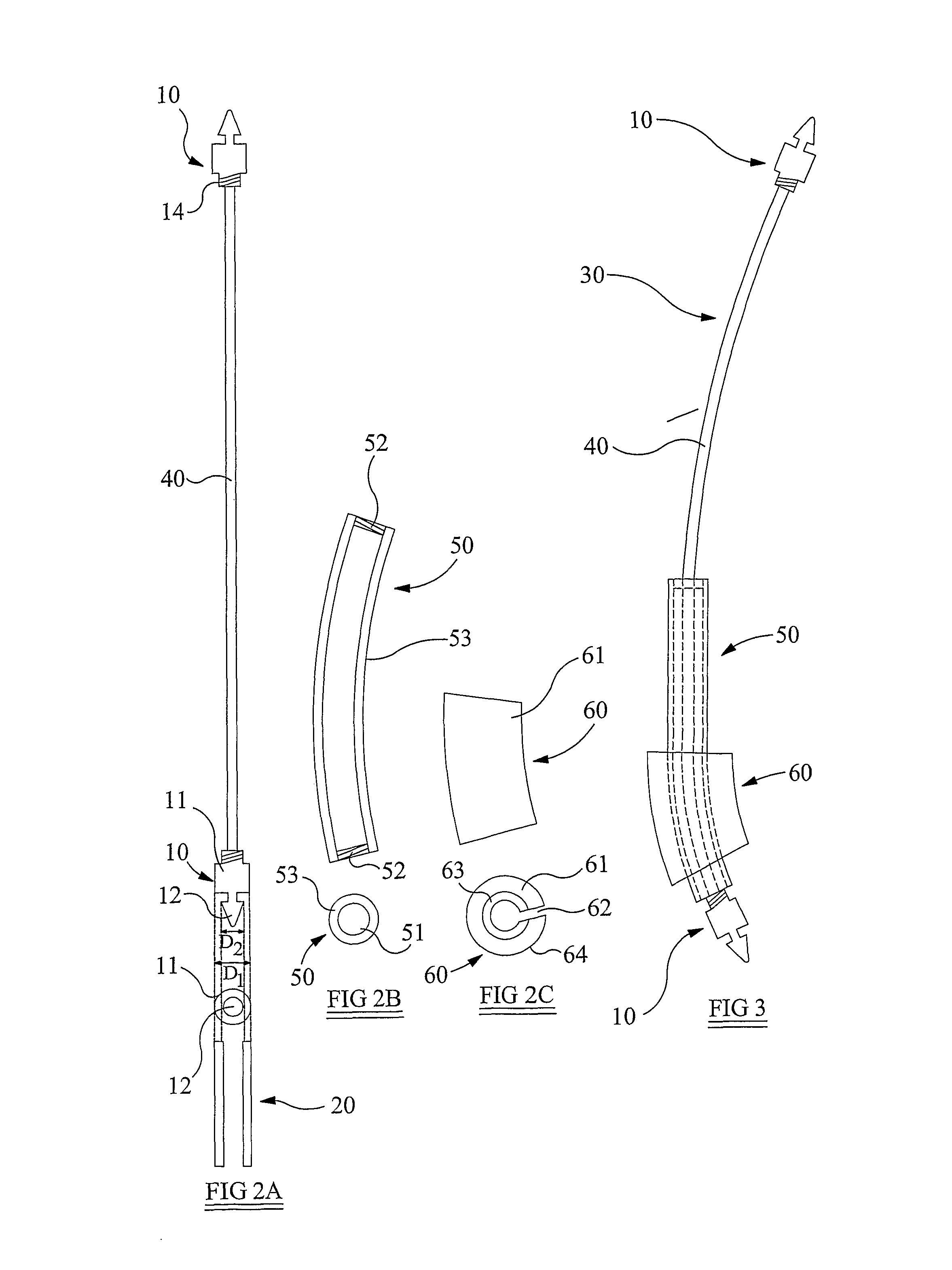
[0075]Referring to the drawings, a tip 10 according to the first aspect of the invention is shown in FIG. 1. The tip 10 comprises an attachment means 14 in the form of a threaded shaft, a first portion 11 proximal to the attachment means 14, a second portion 12 distal to the attachment means 14, and a third portion 13 disposed between the first portion 11 and the second portion 12.

[0076]The attachment means 14 is configured for attaching the tip 10 to a tunnelling instrument 30, as shown in FIG. 3. The first portion 11 includes the greatest diameter D1 of the tip 10. The second portion 12 has a maximum diameter D2, which is less than the maximum diameter D1 of the first portion 11. The third portion 13, as illustrated, has a diameter of less than the second portion 12. Thus, the third portion 13 forms a waist in the tip 10, between the second portion, or head, 12 and the first portion, or body, 11.

[0077]As shown in FIG. 1, a tubular object 20 is attached to the tip 10. The tubular o...


PUM


Abstract

An improved tip and handle for a tunnelling instrument are provided along with an improved tunnelling instrument. The tip is configured for attachment to a tunnelling instrument and includes a first portion configured to form a tunnel, a second portion sized to fit within a tubular component to be placed in the tunnel, and a third portion configured for attachment of the tubular component. The handle is configured to be attached to and detached from a tunneller shaft of a tunnelling instrument, at any point along the length of the tunneller shaft. The tunnelling instrument comprises a pair of tips, a connection means for forming a link between the tips, and a tunneller shaft slidably engagable with the connection means and attachable to either of the tips. Various forms of use of the tunnelling instrument are also disclosed.

Description

[0001]This invention relates to a tunnelling instrument for producing a subcutaneous tunnel between skin and muscle or tissue of a patient, the tunnel extending between respective positions in the patient's body in order to place an article, such as a graft or catheter in a minimally invasive manner. The invention also relates to a method of use of said instrument.[0002]An example of use for a known tunnelling instrument would be the placing of a vascular graft to bypass a diseased vessel or to act as a conduit between an artery and vein for vascular access haemodialysis purposes. Generally the tunnelling instrument would consist of a straight or curved rod made of rigid material, such as steel, with a handle on one end and a blunt tip on the other end. The width of the blunt tip employed would approximate to the internal diameter of the required tunnel, which is ideally equivalent to the outer diameter of the tubular article to be placed in the tunnel.[0003]During the tunnelling pr...

Claims


Application Information

Patent Timeline
Patent Type & Authority Patents(United States)
IPC IPC(8): A61B17/00A61M25/01A61B17/32A61B17/34
CPCA61B17/00234A61M25/0136A61M25/0194A61B17/3468A61B2017/320044
Inventor BRIGHT, CHARLES
Owner PLASMED
Why Eureka
Try Eureka