Forged sideways extrusion

a sideways extrusion and forged technology, applied in forging presses, forging/hammering/pressing machines, manufacturing tools, etc., can solve the problems of limiting the amount of radial expansion that can be obtained in a single forming blow without unacceptable buckling of the blank, process physical limits, and scrap adding significant costs to the process

Active Publication Date: 2015-09-01
THE NAT MASCH CO
View PDF4 Cites 0 Cited by
  • Summary
  • Abstract
  • Description
  • Claims
  • Application Information

AI Technical Summary

Benefits of technology

[0003]The invention involves lateral extrusion of a blank in a workstation in a progressive forming machine. The invention allows various metal parts to be shaped in fewer stations than has been required in the past, can produce parts with lateral extensions exhibiting a high reduction in area and / or a finished thickness and, can reduce a percentage of scrap by eliminating or reducing the amount of material required to be trimmed from asymmetric and / or accircular parts.
[0005]The sliding tool can be mounted on either the ram or the die breast of the progressive forming machine. The spring allows the slidable tool to recede on the part of the machine on which it is mounted while the ram is approaching front dead center (FDC) and displacing blank material through the lateral extrusion aperture.

Problems solved by technology

There are limits to the amount of radial expansion that can be obtained in a single forming blow without unacceptable buckling of the blank.
On the other hand, some parts may require a reduction in area using an extrusion technique but, again, such processes have physical limits, as recognized in the industry.
Still further, to form some irregularly shaped parts using customary processes, it can be necessary to trim a large volume of material from the blank so that the resulting scrap adds significant costs to a process.

Method used


Image

  • Forged sideways extrusion
  • Forged sideways extrusion
  • Forged sideways extrusion

Examples


Embodiment Construction

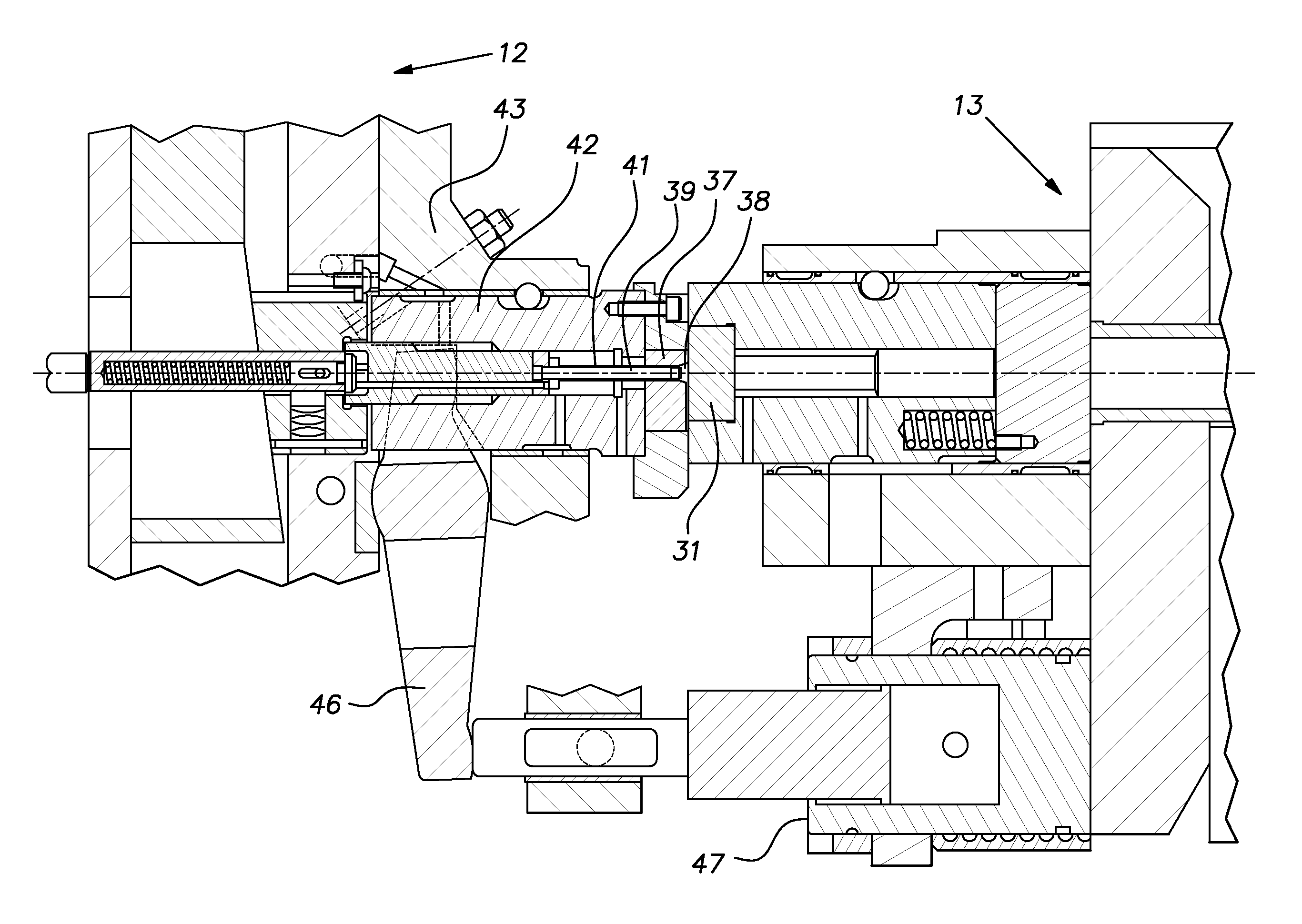
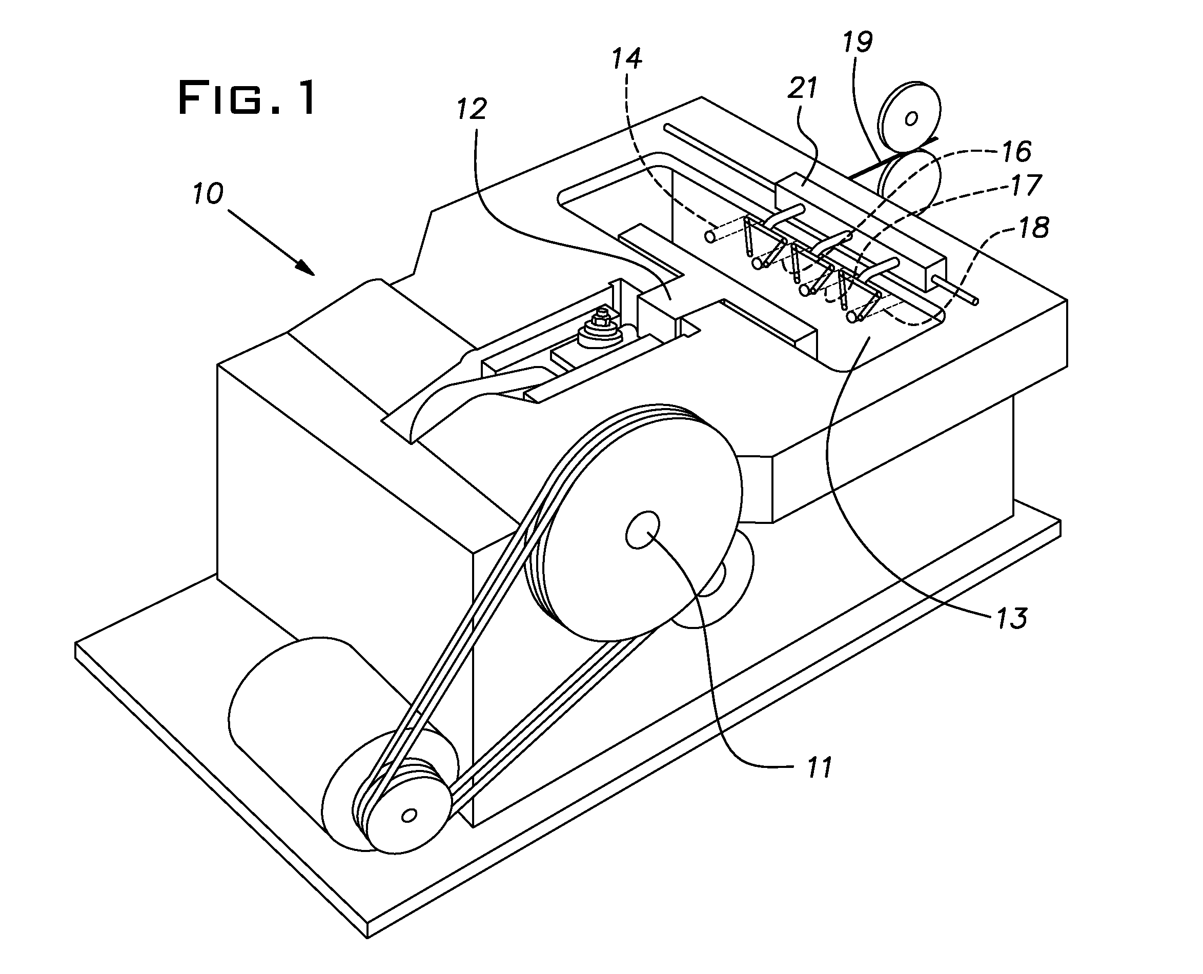
[0010]FIG. 1 schematically illustrates a progressive forming machine 10. Rotation of a crankshaft 11 reciprocates a ram or slide 12 towards and away from a die breast or bolster 13. The machine 10 is shown with uniformly horizontally spaced cutoff station 14 and three workstations 16-18. The invention, as will be understood with those familiar in the art, can be practiced with machines of a different number of stations. In a customary manner, blanks are cut from round wire stock 19 by a shear at the cutoff station 14 and then are transferred by a mechanism 21 to successive stations 16-18 in timed relation to reciprocation of the ram.

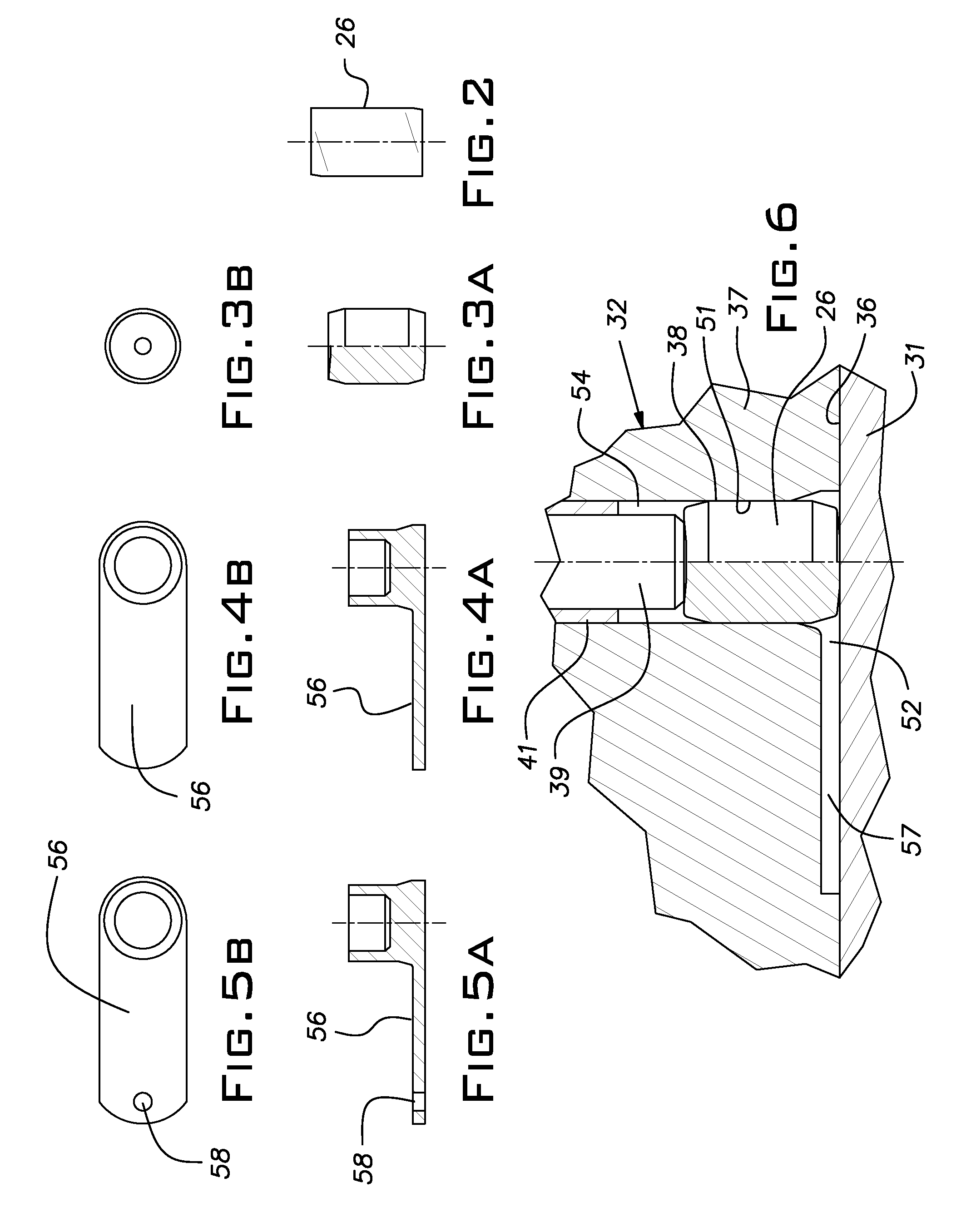
[0011]FIGS. 2-5 illustrate various stages of the forming of a workpiece in an application of the invention. An initial blank 26 produced at the cutoff station 14 is shown in FIG. 2. Typically, the generally cylindrical blank 26 has irregular ends, a result of the shearing process at the cutoff station 14. The blank 26 is struck in a die and punch at the ...


PUM

PropertyMeasurementUnit
pressure forcesaaaaaaaaaa
shapeaaaaaaaaaa
areaaaaaaaaaaa

Abstract

A method and apparatus for forming metal parts in a progressive forming machine wherein one of the opposed tools on a ram and die breast is spring biased to operatively close the tools before the ram reaches front dead center thereby allowing material of the blank to extrude sideways through an aperture formed by both of the opposed tools in the final forward movement of the ram.

Description

BACKGROUND OF THE INVENTION[0001]The invention relates to forming techniques used in progressive metal formers.PRIOR ART[0002]Forging or forming machines have long been used to shape cylindrical blanks into more complex shapes. A common forming method involves upsetting or coning dies in which a blank is axially compressed to expand it radially. There are limits to the amount of radial expansion that can be obtained in a single forming blow without unacceptable buckling of the blank. Consequently, in a progressive former, several stations may be required to produce a desired radially extending shape. On the other hand, some parts may require a reduction in area using an extrusion technique but, again, such processes have physical limits, as recognized in the industry. Still further, to form some irregularly shaped parts using customary processes, it can be necessary to trim a large volume of material from the blank so that the resulting scrap adds significant costs to a process.SUMM...

Claims


Application Information

Patent Timeline
Patent Type & Authority Patents(United States)
IPC IPC(8): B21J5/02B21C23/18B21C23/00B21D19/08B21J9/02B30B3/02B21D51/14
CPCB21J5/025B21C23/001B21C23/183B21D19/082B21D19/088B21D51/14B21J5/02B21J9/022B21J9/027B30B3/02B21J13/02B21K1/76
Inventor BORDNER, MARK W.
Owner THE NAT MASCH CO
Why Eureka
Try Eureka