Pneumatic tire

a pneumatic tire and weight reduction technology, applied in the field of pneumatic tires, can solve the problems of reducing the intended effect and reducing the proportion, and achieve the effect of reducing weight, excellent steering stability and durability

Inactive Publication Date: 2015-09-01
BRIDGESTONE CORP
View PDF14 Cites 0 Cited by
  • Summary
  • Abstract
  • Description
  • Claims
  • Application Information

AI Technical Summary

Benefits of technology

[0007]In this structure, however, the rigidity near the recessed portion degrades, making it necessary to guarantee steering stability. With respect to this point, the technique disclosed in Patent Literature 1 attempts to maintain good steering stability by guaranteeing side rigidity through the further provision of one or more cord reinforcing layers on the outside of the carcass. This approach, however, may diminish the intended effect of reducing the weight of the tire.
[0008]Accordingly, while reducing the weight of the tire by providing a recessed portion in the side rubber near the bead portion, it is important simultaneously to maintain the steering stability at a high level.
[0009]It is therefore an object of the present invention to provide a pneumatic tire that makes reduced weight compatible with steering stability and durability.
[0010]Upon studying the cause of impaired steering stability in a pneumatic tire provided with a recessed portion in the side rubber near the bead portion, the inventor discovered that the main reason is that the side rigidity of the tire degrades, so that when a lateral force is applied to the tire, collapsing deformation of the sidewall portion starting at the recessed portion occurs more easily.
[0011]With regard to a method for guaranteeing a high level of steering stability in a pneumatic tire provided with a recessed portion in the side rubber near the bead portion, the inventor then discovered that from the perspective of suppressing the above-described collapsing deformation of the sidewall portion, the side rigidity of the tire can be guaranteed by setting the carcass line in accordance with the curvature of a circle that defines the outline of the recessed portion. In other words, the inventor completed the present invention through the discovery that by setting the carcass line in accordance with the curvature of the recessed portion, the resultant force with which the air inside the tire pushes the tire inner surface outward in the width direction increases in a region from the bead portion to the sidewall portion when the tire is filled with air, and the rigidity from the bead portion to the sidewall portion rises, thereby suppressing collapse of the sidewall portion.
[0014]According to the present invention, it is possible to provide a pneumatic tire that, while achieving sufficiently reduced weight by providing a recessed portion in the side rubber near the bead portion, guarantees excellent steering stability and durability.

Problems solved by technology

In this structure, however, the rigidity near the recessed portion degrades, making it necessary to guarantee steering stability.
This approach, however, may diminish the intended effect of reducing the weight of the tire.

Method used


Image

  • Pneumatic tire
  • Pneumatic tire
  • Pneumatic tire

Examples


examples

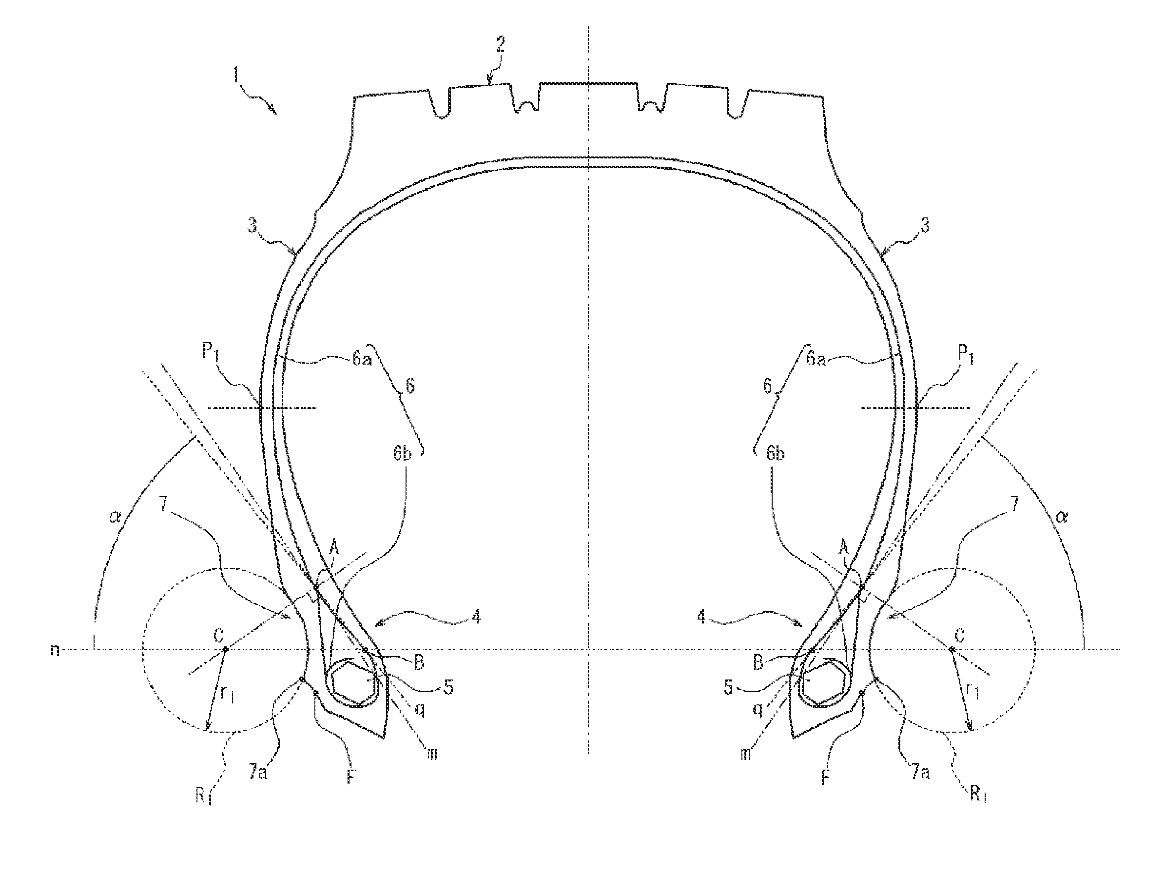
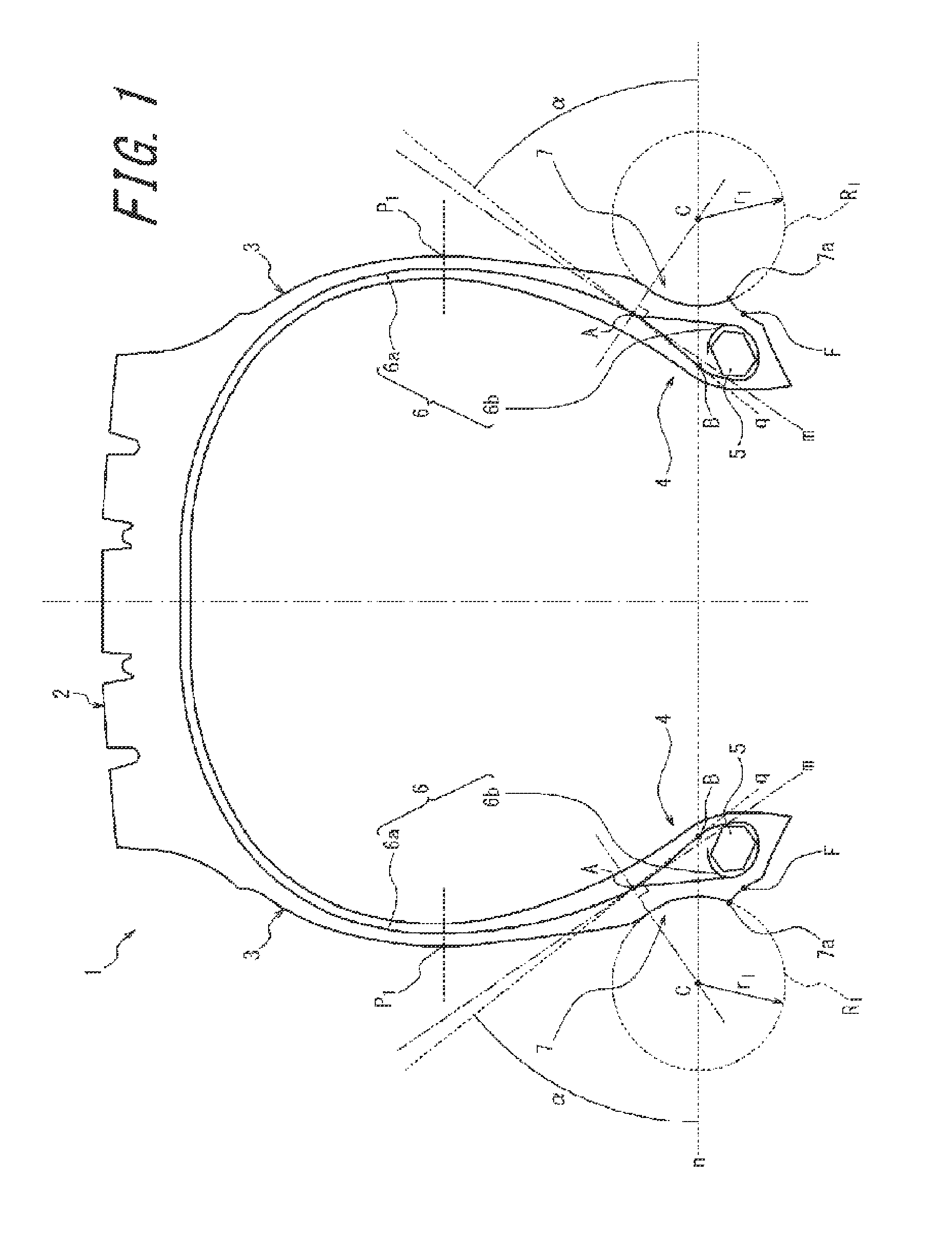
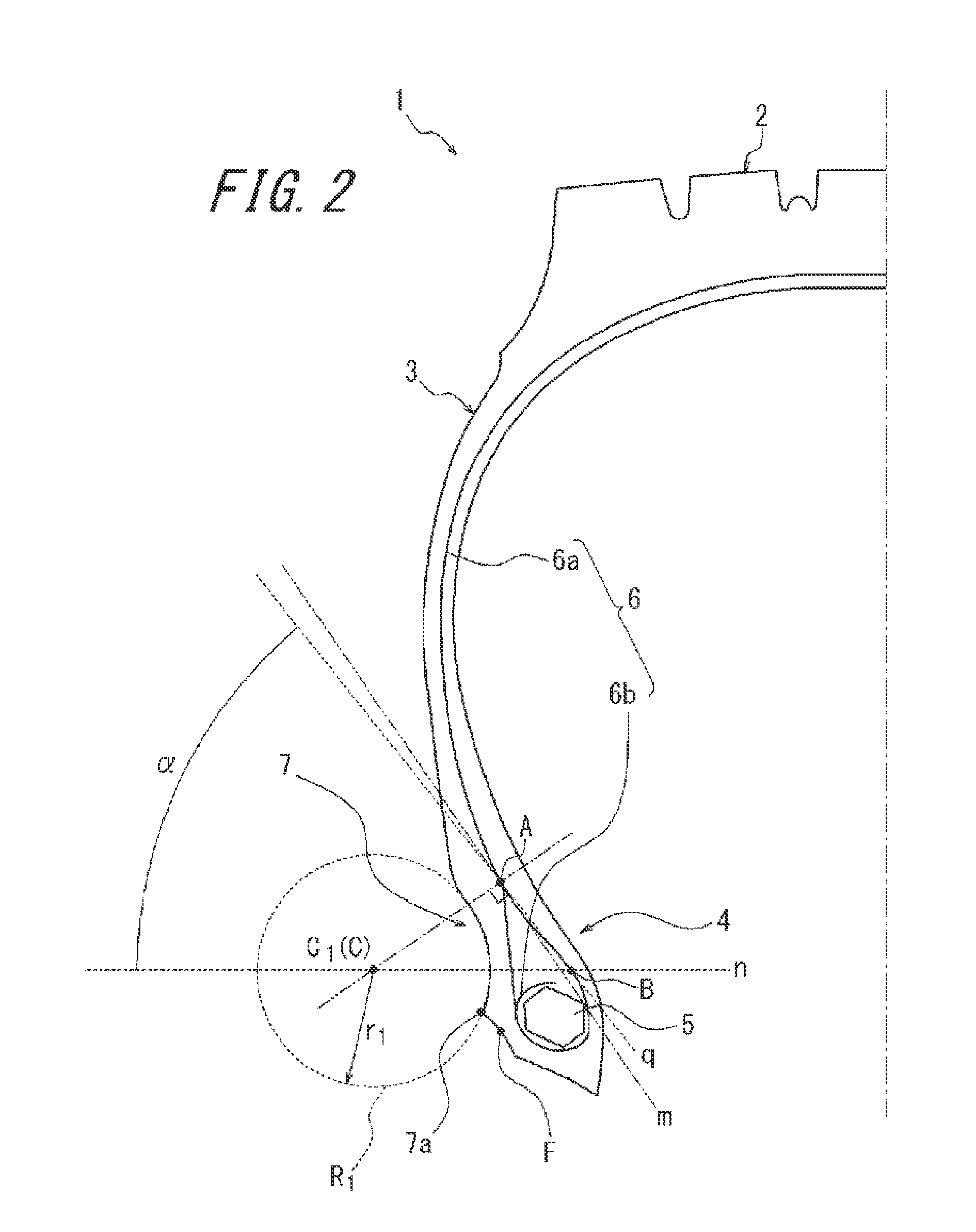
[0056]Next, Inventive Example Tires 1 to 3 were produced to have a tire size of 275 / 80R22.5, and as illustrated in FIG. 1, to have a recessed portion within the region from the rim separation point to the tire maximum width position, the angle of elevation of the intersection point A being from 40° to 60°. The specifications were as listed in Table 1.

[0057]Comparative Example Tires 1 to 6 were also produced to have a similar recessed portion as Inventive Example Tire 1 and to have the specifications listed in Table 1. Note that the amount of reduction in tire weight (kg) is the amount of reduction from a tire not having the recessed portion, i.e. the rubber weight (kg) corresponding to the recessed portion.

[0058]

TABLE 1InventiveInventiveInventiveComparitiveComparitiveComparitiveComparitiveComparitiveComparitiveConven-ExampleExampleExampleExampleExampleExampleExampleExampleExampletionalTire 1Tire 2Tire 3Tire 1Tire 2Tire 3Tire 4Tire 5Tire 6TireRadius of 204060805100406060N / Acurvature ...


PUM


Abstract

An angle of elevation (α) of an intersection point (A), formed between a line (q) connecting intersection points (A, B) and a reference line (n) traversing a center of curvature (C) of an arc and parallel to the tire rotation axis, is from 40° to 60°, where a curve tracing the innermost region in the tire radial direction is approximated by the arc with the method of least squares, the intersection point (A) is an intersection point of the ply main body (6a) with a normal line (m) from the center of curvature (C) of the arc to a part of the ply main body (6a) convex outward in the tire width direction, and the intersection point (B) is an intersection point of the ply main body (6a) with the reference line (n). A radius of curvature of the arc is from 5 mm to 80 mm.

Description

CROSS REFERENCE TO RELATED APPLICATIONS[0001]This application is a National Stage of International Application No. PCT / JP2013 / 000304 filed Jan. 23, 2013, claiming priority based on Japanese Patent Application No. 2012-012282 filed Jan. 24, 2012, the contents of all of which are incorporated herein by reference in their entirety.TECHNICAL FIELD[0002]The present invention relates to a reduced weight pneumatic tire provided with a recessed portion by hollowing out part of the side rubber near a bead portion.BACKGROUND ART[0003]In recent years, out of consideration for the environment and from an economical perspective, there has been a demand for improvement in the fuel efficiency of automobiles. Against this background, there is a desire to reduce the rolling resistance of tires. Therefore, the weight of the structural components and members of tires is being reduced.[0004]In particular, one effective way of lowering the weight of the tire is to reduce the amount of rubber used. For e...

Claims


Application Information

Patent Timeline
Patent Type & Authority Patents(United States)
IPC IPC(8): B60C3/00B60C15/024B60C13/00B60C13/02
CPCB60C13/003B60C3/00B60C13/00B60C13/02B60C15/024B60C15/0027B60C15/0242B60C2200/06
Inventor KURITA, KEIICHI
Owner BRIDGESTONE CORP
Why Eureka
Try Eureka