Monitoring air filter status in automotive HVAC system

a technology for monitoring the status of air filters and hvac systems, applied in the direction of vessel parts, separation processes, vessel construction, etc., can solve the problems of inconvenient maintenance, inconvenient use, and insufficient packaging space for replacement filters, so as to avoid the cost, weight and packaging space of separate sensors and their associated wiring and structural features, and reduce ventilation performance. , the effect of saving the user

Active Publication Date: 2015-09-01
FORD GLOBAL TECH LLC
View PDF24 Cites 5 Cited by
  • Summary
  • Abstract
  • Description
  • Claims
  • Application Information

AI Technical Summary

Benefits of technology

[0006]The present invention monitors for a clogged or unclogged state of an air filter without requiring a separate filter-check sensor, thereby avoiding the cost, weight, and packaging space of a separate sensor and its associated wiring and structural features. A reminder for replacing the air filter is made only when it is actually needed, thereby saving the user from either unnecessary filter changes or decreased ventilation performance when a needed replacement is delayed.

Problems solved by technology

These replaceable filters need to be changed when they become clogged with filtered particles and dirt.
Such systems have proven costly and consume packaging space that is in short supply.
They also add complexity to the manufacturing of the automotive heating, ventilation, and air conditioning (HVAC) system.
Consequently, many vehicles are manufactured without any automatic monitoring of the state of the air filter.
These recommendations are determined based upon average conditions, so any particular user may have a clogged filter before expiration of the recommended interval or they may end up replacing an unclogged filter unnecessarily.
However, such prior systems have been unreliable and have been found to give inaccurate results due to failures to recognize and control all significant variables impacting the air flow.

Method used


Image

  • Monitoring air filter status in automotive HVAC system
  • Monitoring air filter status in automotive HVAC system
  • Monitoring air filter status in automotive HVAC system

Examples


Embodiment Construction

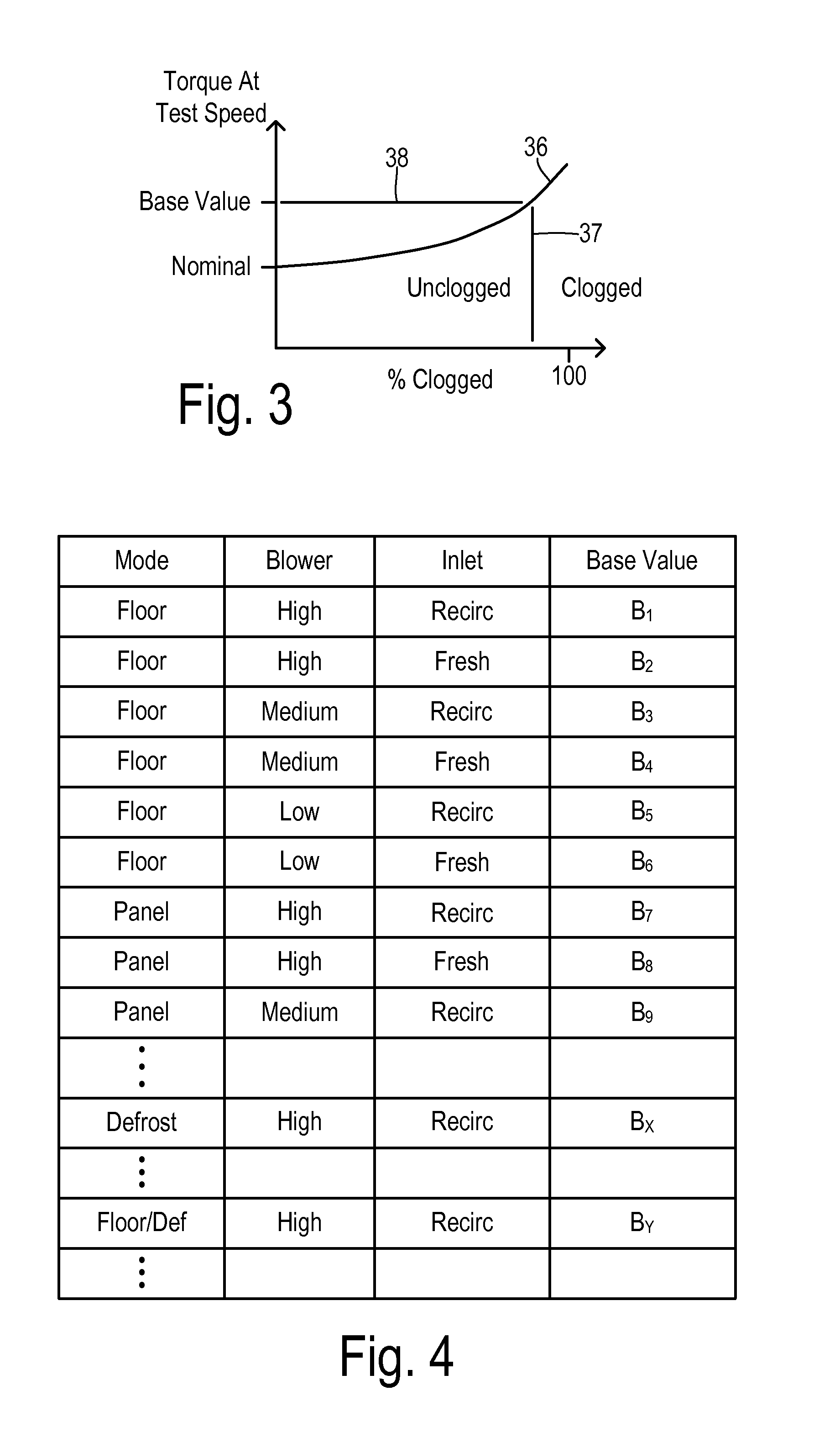
[0018]The present invention uses a speed-controlled blower motor wherein the energization required to obtain a particular motor speed is compared to the energization required when an unclogged filter is present. Importantly, the HVAC system is placed into a baseline condition (i.e., a predetermined configuration including a mode of distribution of the airflow) so that variabilities in the airflow not caused by the air filter state are minimized. In particular, moisture accumulation on the evaporator core has been found to significantly influence the resistance to airflow through the HVAC system. Therefore, the baseline condition includes applying a moisture purge to the evaporator.

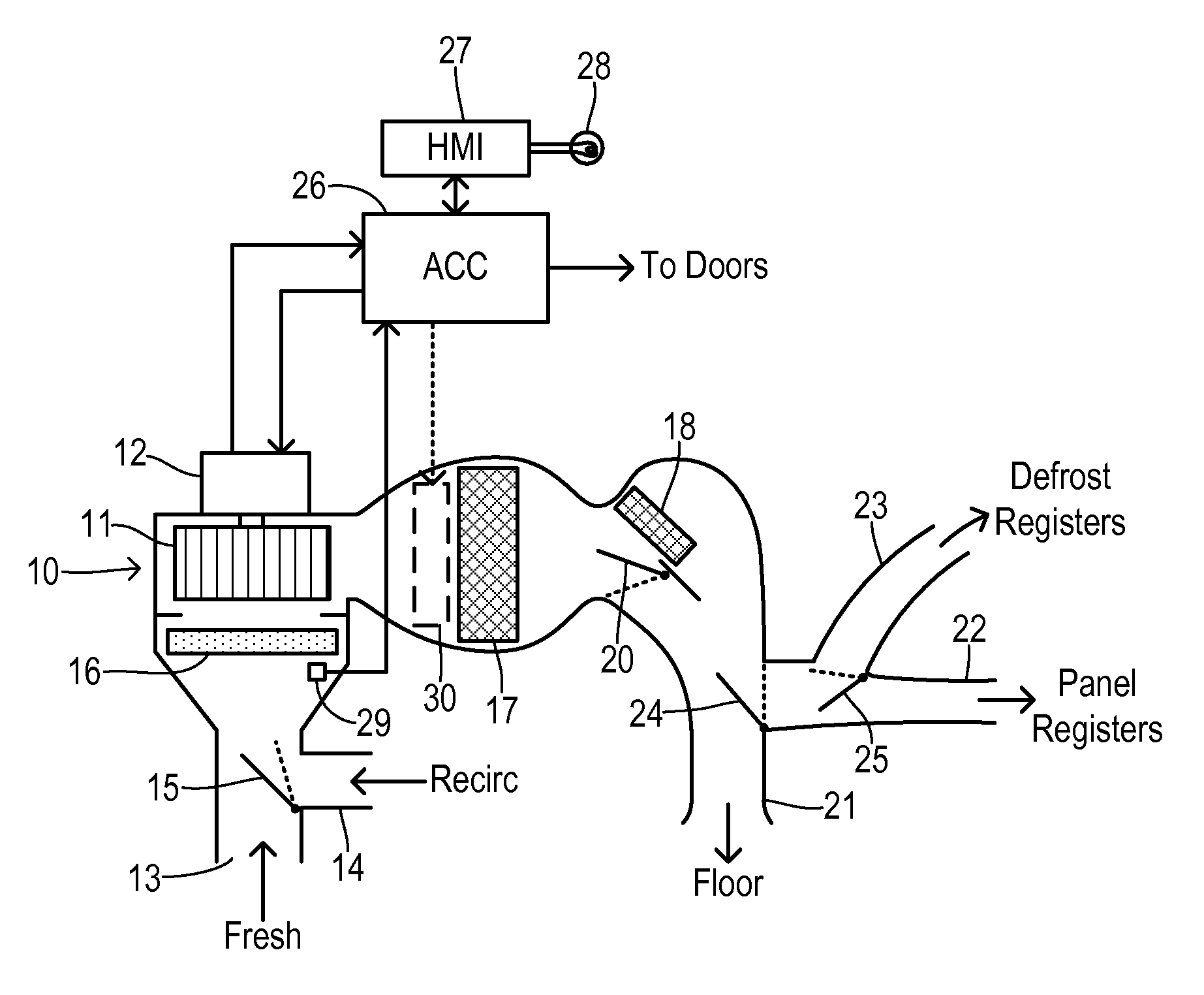
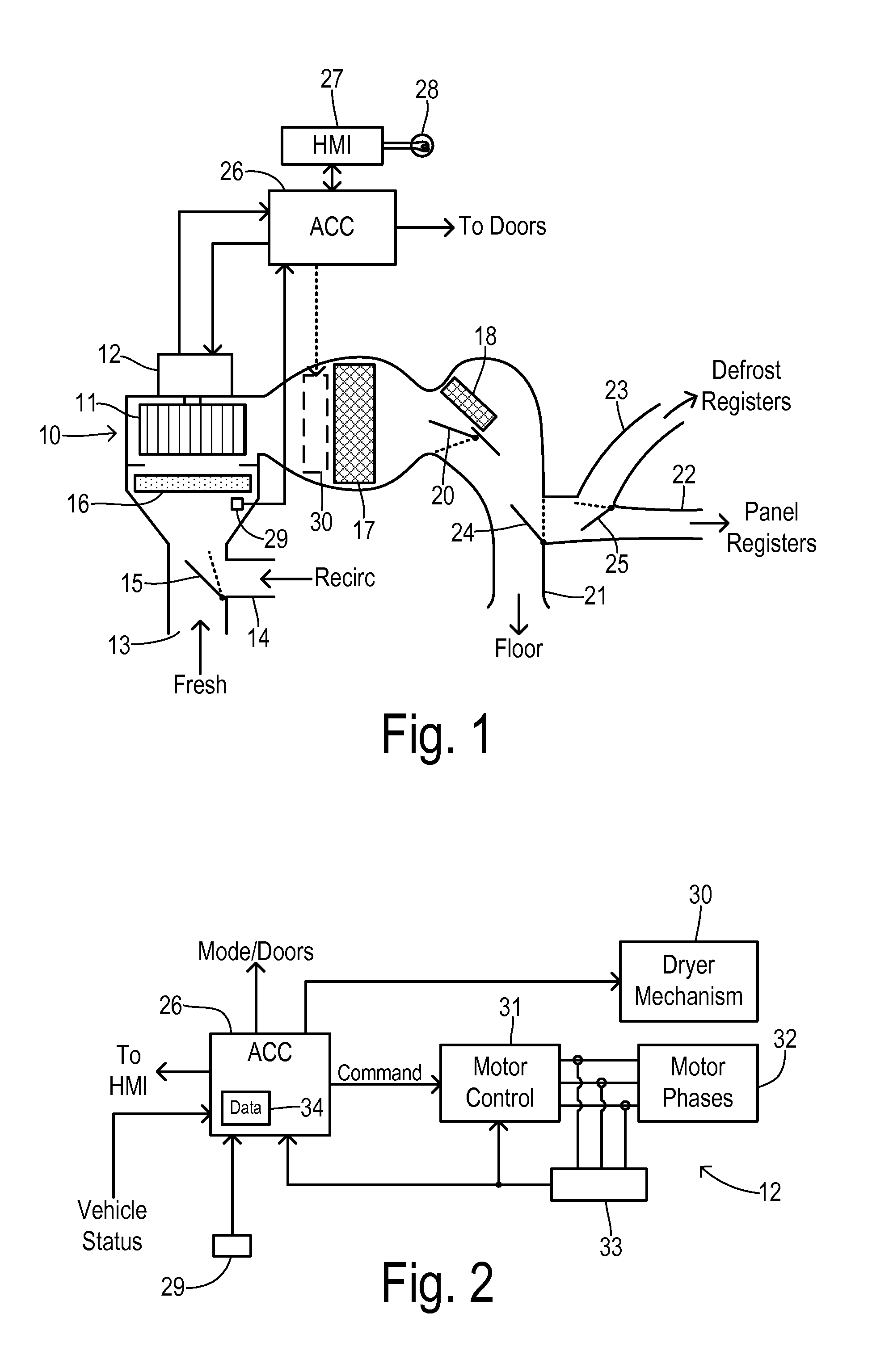
[0019]An example system for implementing the present invention is shown in FIG. 1. An HVAC system includes an air handling case 10 having a blower fan 11 driven by a blower motor 12. Blower fan 11 receives either fresh air from an inlet 13 and / or recirculated interior air from an inlet 14 as determined by ...


PUM

PropertyMeasurementUnit
speedaaaaaaaaaa
torqueaaaaaaaaaa
currentaaaaaaaaaa

Abstract

A system and methods are provided for monitoring for a clogged or unclogged state of an air filter in an automotive HVAC system. The HVAC system includes a blower having a blower motor providing a driven airflow. A plurality of outlet registers is controllable to provide a plurality of circulation modes. An evaporator selectably cools the driven airflow, and the air filter passes the driven airflow. The method enters a baseline condition, wherein the baseline condition includes applying a moisture purge to the evaporator and selection of a predetermined circulation mode. The blower motor is controlled to maintain a testing speed. An energization of the blower motor is quantified while maintaining the testing speed. The energization is compared to a base value derived according to the baseline condition with the air filter in an unclogged state. A replacement action is triggered when the energization is greater than the base value.

Description

CROSS REFERENCE TO RELATED APPLICATIONS[0001]Not Applicable.STATEMENT REGARDING FEDERALLY SPONSORED RESEARCH[0002]Not Applicable.BACKGROUND OF THE INVENTION[0003]The present invention relates in general to cabin air filters for automotive vehicles, and, more specifically, to detecting when an air filter has become clogged and is in need of replacement.[0004]Because of the potential for airborne contaminates, cabin air filters are often included in the ventilation systems of automotive vehicles. These replaceable filters need to be changed when they become clogged with filtered particles and dirt. Dedicated sensing systems are known that can identify the filter state and provide an indication to the user to let them know when an air filter needs to be replaced. The known prior art systems have used combinations of dedicated sensors (such as a pressure sensor for determining pressure drop across a filter) and special housing design features (such as an air bypass channel). Such system...

Claims


Application Information

Patent Timeline
Patent Type & Authority Patents(United States)
IPC IPC(8): B60H3/06
CPCB60H3/0616B60H2003/0683
Inventor HOKE, PAUL B.JOHNSTON, WILLIAM S.HURD, JAMES R.
Owner FORD GLOBAL TECH LLC
Why Eureka
Try Eureka