
Temperature throttling mechanism for DDR3 memory

a temperature throttling mechanism and memory technology, applied in the field of memory controller design, can solve problems such as reduced thermal output, prone to operational variance, and potential memory-related reliability issues, and achieve the effect of optimal combination of performance and safety

Active Publication Date: 2015-09-01
ADVANCED MICRO DEVICES INC
View PDF13 Cites 5 Cited by
  • Summary
  • Abstract
  • Description
  • Claims
  • Application Information

AI Technical Summary

Benefits of technology

The patent describes a method for controlling a bus, like a memory bus, to ensure that devices on the bus do not overheat and cause damage. The method uses signals from the devices or temperature measurements to determine when the devices are too hot. A memory controller uses these signals to throttle the bus, which helps improve its performance while keeping the devices cool. The method combines fixed percentage throttling and rampdown / rampup throttling based on different conditions, which provides better performance and safety compared to a single fixed throttling algorithm for each memory controller.

Problems solved by technology

Many digital systems, especially those that include high-performance, high-speed circuits, are prone to operational variances due to temperature effects.
Typically, especially in today's ever-faster systems, if left unchecked, memory devices (e.g. DDR) may start running above their maximum operating temperatures, resulting in potential memory-related reliability issues.
Memory throttling generally provides a solution to cool the memory devices by reducing memory traffic allowed on the memory bus, thereby reducing the power consumed by the memory devices, which leads to reduced thermal output.
While in many cases, semiconductor-based temperature sensing methods are employed to obtain readings corresponding to temperature values, there may be cases when the obtained readings, while related to temperature, do not directly correspond to actual temperature values.

Method used


Image

  • Temperature throttling mechanism for DDR3 memory
  • Temperature throttling mechanism for DDR3 memory
  • Temperature throttling mechanism for DDR3 memory

Examples


Embodiment Construction

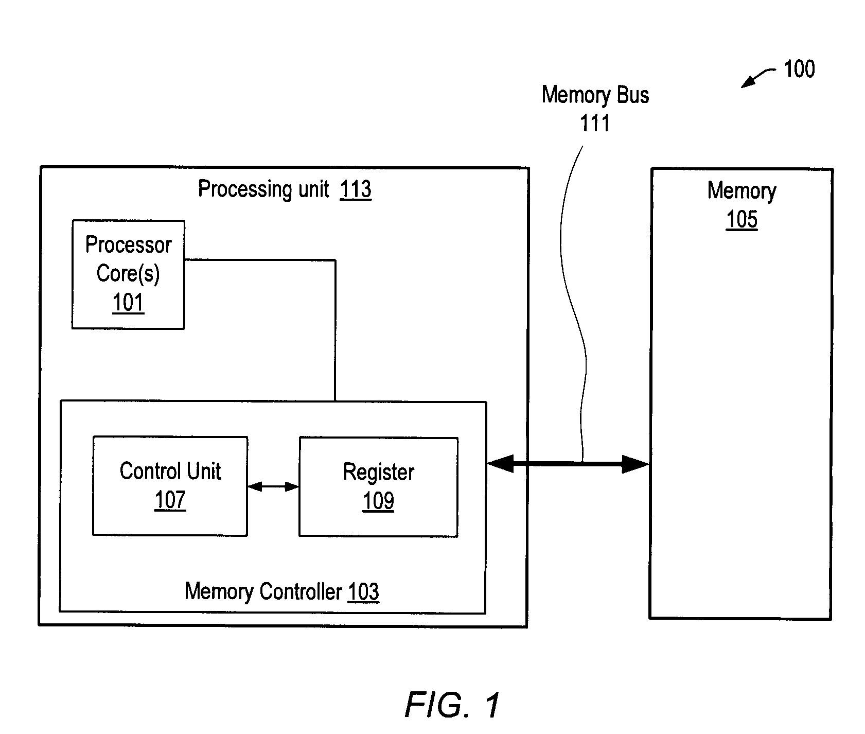
[0024]FIG. 1 shows a block diagram of a basic exemplary system 100, which may be a computer system, in which a processing unit 100 is configured with a processor core 101, coupled to a memory controller 103. Memory controller 103 may be coupled to a memory bus 111, through which memory controller 103 may regulate access to memory 105, to facilitate data exchange between processing unit 100 and memory 105. Those skilled in the art will appreciate that system 100 may be implemented in a variety of ways, and is shown simply to illustrate a basic configuration in which memory access is controlled by a memory controller.

[0025]In one set of embodiments, memory controller 103 may comprise a control unit 107 coupled to an internal register 109. Various embodiments of memory controller 103 may include other subcircuits and / or components, including additional registers for supporting a range of functionality as required by the needs of system 100. For example, memory controller 103 may includ...


PUM


Abstract

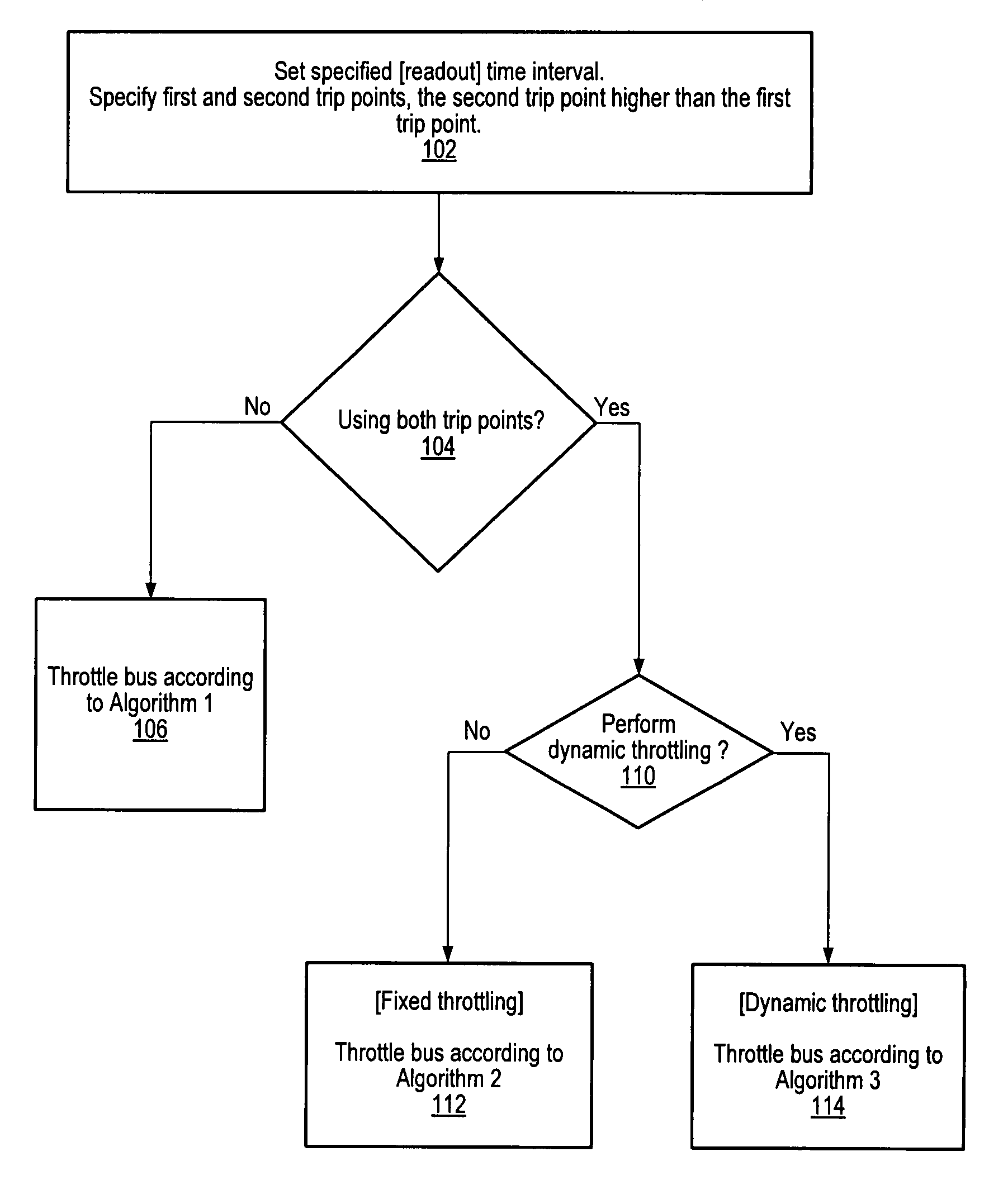
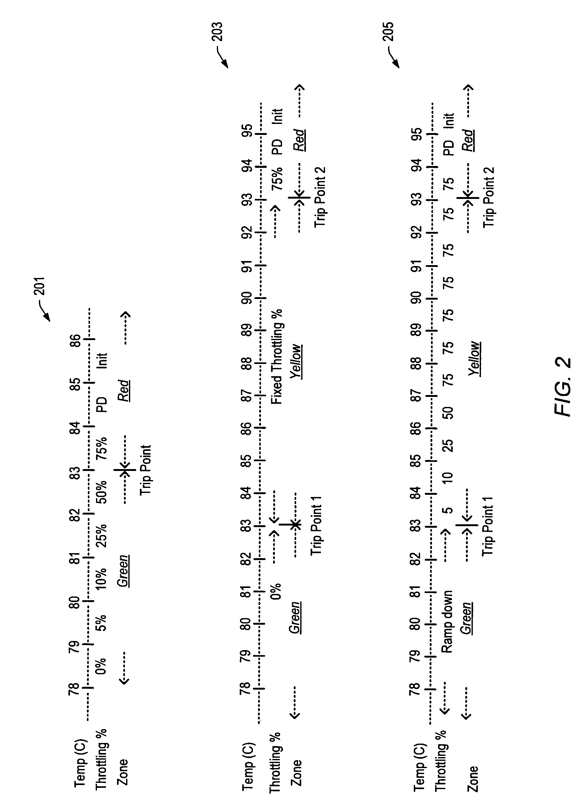
A method for throttling a bus, e.g. a memory bus, may be used to compensate for potential inaccuracy of feedback information received for monitored characteristics, e.g. temperature, reported by sensors configured in monitored devices, e.g. memory devices, accessed through the bus. For example, in case of a memory bus, a memory controller may be configured to throttle the memory bus in a way that maximizes system performance while ensuring that the memory devices keep operating within their thermal limits. Readings obtained from the memory, or from close proximity to the memory, may indicate whether the temperature of the memory has crossed over one or more designated trip points, and one or more algorithms may be executed to perform throttling according to the readings and based on fixed and dynamic throttling modes. The memory controller may infer temperature changes taking place in the memory devices when successive readings are indicating that the temperature of the memory device has remained over a given trip point. Based on these inferences, the memory controller may then change the manner in which the bus is throttled.

Description

BACKGROUND OF THE INVENTION[0001]1. Field of the Invention[0002]This invention relates generally to the field of memory controller design and, more particularly, to the design of a temperature throttling mechanism for safe and efficient memory operation.[0003]2. Description of the Related Art[0004]Many digital systems, especially those that include high-performance, high-speed circuits, are prone to operational variances due to temperature effects. Devices that monitor temperature and voltage are often included as part of such systems in order to maintain the integrity of the system components. Personal computers (PC), signal processors and high-speed graphics adapters, among others, typically benefit from such temperature monitoring circuits. For example, a central processor unit (CPU) that typically “runs hot” as its operating temperature reaches high levels may require a temperature sensor in the PC to insure that it doesn't malfunction or break due to thermal problems.[0005]Ofte...

Claims


Application Information

Patent Timeline
Patent Type & Authority Patents(United States)
IPC IPC(8): G06F3/00G06F13/16
CPCG06F13/161
Inventor ASKAR, TAHSINMADRID, PHILIP E.
Owner ADVANCED MICRO DEVICES INC
Learn More