Apparatus and related method for the recovery and the pneumatic transportation of dust coming from a filtration system

a technology of filtration system and equipment, applied in the direction of conveying, dispersed particle separation, separation process, etc., can solve the problems of increasing the height of the filter, cost and space, and requiring considerable manpower, and achieve the effect of convenient and economical production

Active Publication Date: 2015-09-08
WAM IND
View PDF22 Cites 18 Cited by
  • Summary
  • Abstract
  • Description
  • Claims
  • Application Information

AI Technical Summary

Benefits of technology

[0010]The purpose of the present invention is, therefore, to provide an apparatus for the pneumatic removal of dust from a filtration system which overcomes the drawbacks described above and which is, at the same time, easy and economical to produce.

Problems solved by technology

In many cases, the evacuation system of the filtered particulate must be overscaled as it is necessary to empty the bottom of the hopper in the shortest time possible, with evident problems in terms of cost and space (in some cases, the height of the filter must be increased).
This operation therefore involves the use of considerable manpower and exposure of the operators to contact and / or inhalation of particulate present in the transfer recipient.
Moreover, the particulate must then be transferred into larger containers with a further loss of time and further exposure of the operators to the particulate.
Furthermore, a portion of particulate may be dispersed in the surrounding environment with evident negative effects on this.
As there may be a large number of filters in production plants, the cost of labour and frequency of exposure to dust are significant.
The problem of emptying filters mainly arises with extraction filters (i.e. with internal pressure drop).

Method used


Image

  • Apparatus and related method for the recovery and the pneumatic transportation of dust coming from a filtration system
  • Apparatus and related method for the recovery and the pneumatic transportation of dust coming from a filtration system

Examples


Embodiment Construction

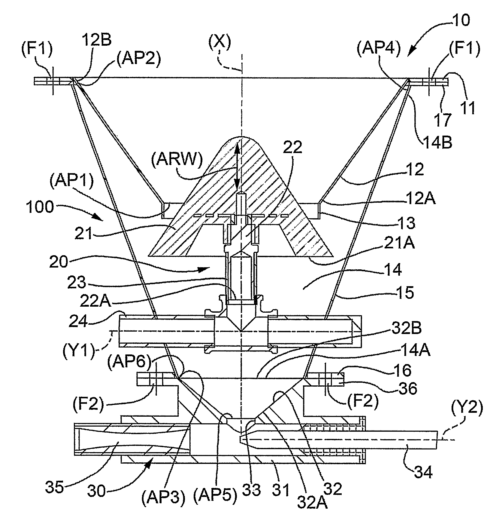
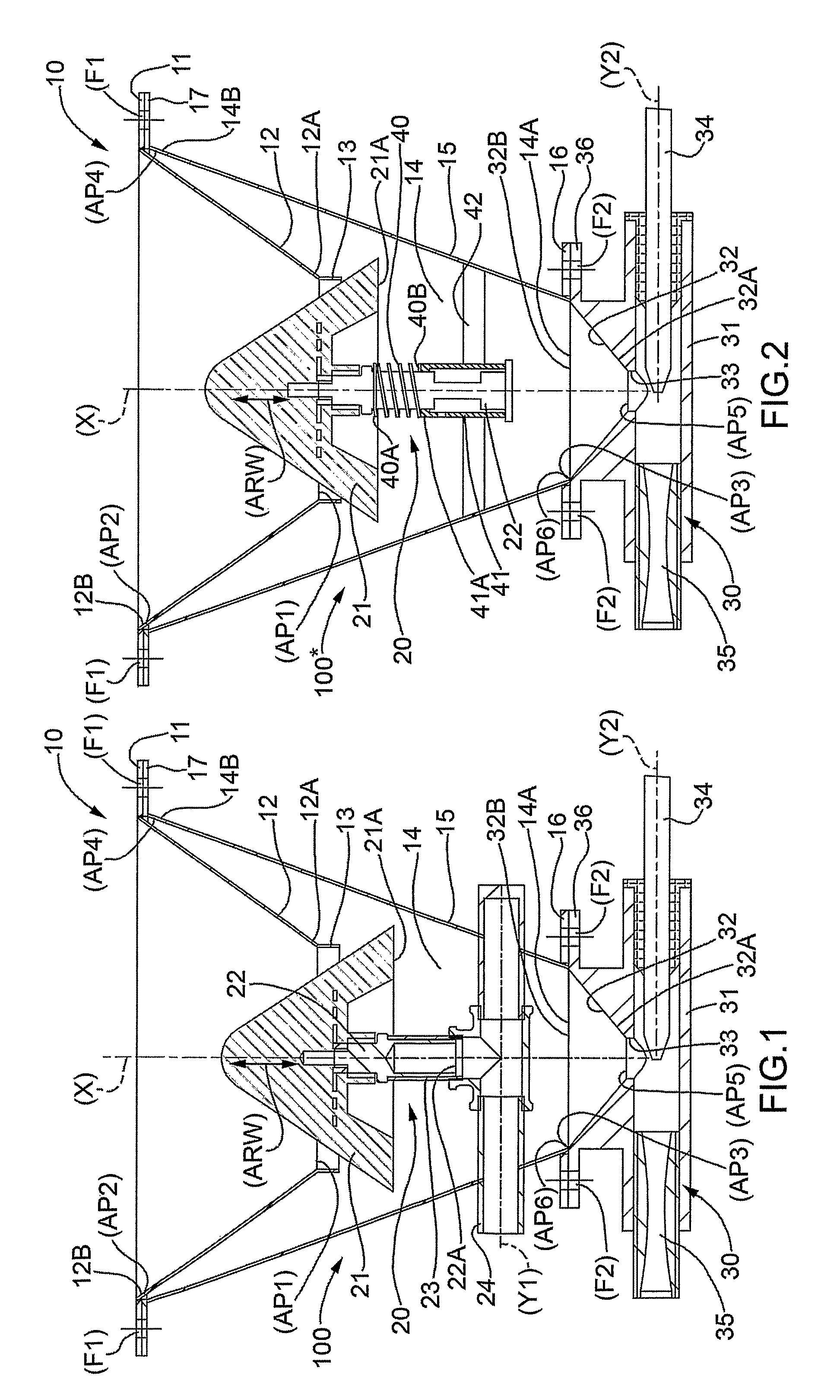
[0020]In FIG. 1, designated as a whole by number 100 is an innovative apparatus for pneumatic dust removal of an overhead filtration system 10.

[0021]The filtration system 10 comprises, in a conventional manner, a filter (not shown in the figure) fitted on an upper flange 11 of a hopper 12 for collection of dust coming from said filter.

[0022]As shown in FIG. 1, the hopper 12 is of an “inverted” truncated cone shape, in that the smaller base 12A of the truncated cone is arranged below the larger base 12B of said truncated cone.

[0023]At the position of the smaller base 12A, there is an opening (AP1) through which the dust is discharged from the hopper 12 towards an evacuation system (see below).

[0024]Similarly, the upper base is characterised by an opening (AP2) that connects the filter and the hopper 12.

[0025]The smaller base envisages, advantageously, a cylindrical collar 13.

[0026]Below and around the hopper 12, there is an intermediate chamber 14, also advantageously but not necessa...


PUM

PropertyMeasurementUnit
pressureaaaaaaaaaa
pressure dropaaaaaaaaaa
elastic forceaaaaaaaaaa

Abstract

An apparatus and related method for the recovery and the pneumatic transportation of dust coming from a filtration system provided with a particulate collection hopper. The apparatus comprises:an intermediate chamber for the passage of the particulate towards the evacuation means; andshutting means for a bottom opening (AP1) of said hopper. The apparatus is characterized in that the shutting means comprise, in turn, a shutter moved according to an arrow (ARW) by the action of intermittent pressurized air that flows in a control conduit forming part of said shutting means. Furthermore, the evacuation means comprise elements, specifically a nozzle aligned with a Venturi, to produce a pressure drop in the intermediate chamber.

Description

TECHNICAL FIELD[0001]The present invention relates to an apparatus and related method for the pneumatic recovery of dust coming from a filtration system.BACKGROUND ART[0002]As is known, the hopper of a filter collects the dust that is extracted and filtered until the extractor can be switched off (for example, at the end of the shift or at the end of the working day). Immediately after switching off, a closing valve of the discharge of the hopper is opened and the filtered particulate is evacuated, by means of a screw or a pneumatic transportation system, towards another collection system.[0003]In many cases, the evacuation system of the filtered particulate must be overscaled as it is necessary to empty the bottom of the hopper in the shortest time possible, with evident problems in terms of cost and space (in some cases, the height of the filter must be increased).[0004]In any case, the most common system for evacuation of the filtered particulate envisages the use of a 50-75 lite...

Claims


Application Information

Patent Timeline
Patent Type & Authority Patents(United States)
IPC IPC(8): B65G53/36B01D46/48B65G53/14
CPCB65G53/14B01D46/48
Inventor MARCHESINI, VAINERGOLINELLI, LUCA
Owner WAM IND
Why Eureka
Try Eureka