Eureka AIR delivers breakthrough ideas for toughest innovation challenges, trusted by R&D personnel around the world.

Gear pump

a technology of gear pump and gear body, which is applied in the direction of liquid fuel engines, machines/engines, rotary piston liquid engines, etc., can solve the problems of adhesive wear on some areas of tooth surfaces, and achieve the effects of less adhesion, less adhesive wear, and reduced occurrence of adhesive wear

Active Publication Date: 2015-09-08
HONDA MOTOR CO LTD +1
View PDF11 Cites 0 Cited by
  • Summary
  • Abstract
  • Description
  • Claims
  • Application Information

AI Technical Summary

Benefits of technology

[0007]According to the present invention, one of the driving rotor and the driven rotor of the gear pump is given the steam treatment while the other remains untreated. The desired hardness of the tooth surface (contacting surface) of the one rotor can be therefore secured while the hardness of the tooth surface (contacting surface) of the other rotor is relatively low. As a result, possible occurrence of adhesive wear and delamination of a tooth surface is reduced. For example, as for adhesive wear, because the adhesion temperature of members of different materials in contact with each other is high, there is a less incidence of adhesion, and thus, the occurrence of adhesive wear is reduced. Also, as for delamination of a tooth surface, because one of the driving rotor and the driven rotor, which is more likely to be subject to delamination of a tooth surface than the other, remains untreated, embrittlement of the tooth surface is prevented, and thus, the occurrence of delamination of the tooth surface can be reduced. In a preferred embodiment, because either the driving rotor or the driven rotor is appropriately selected to be given the steam treatment, an appropriate effect can be obtained.

Problems solved by technology

In this case, it has been found that although the tooth surfaces do not wear during a normal operation of the pump, adhesive wear occurs on some areas of the tooth surfaces during a continuous actuation of the pump, depending on a temperature range and / or a rotational speed range.

Method used


Image

  • Gear pump
  • Gear pump
  • Gear pump

Examples


Embodiment Construction

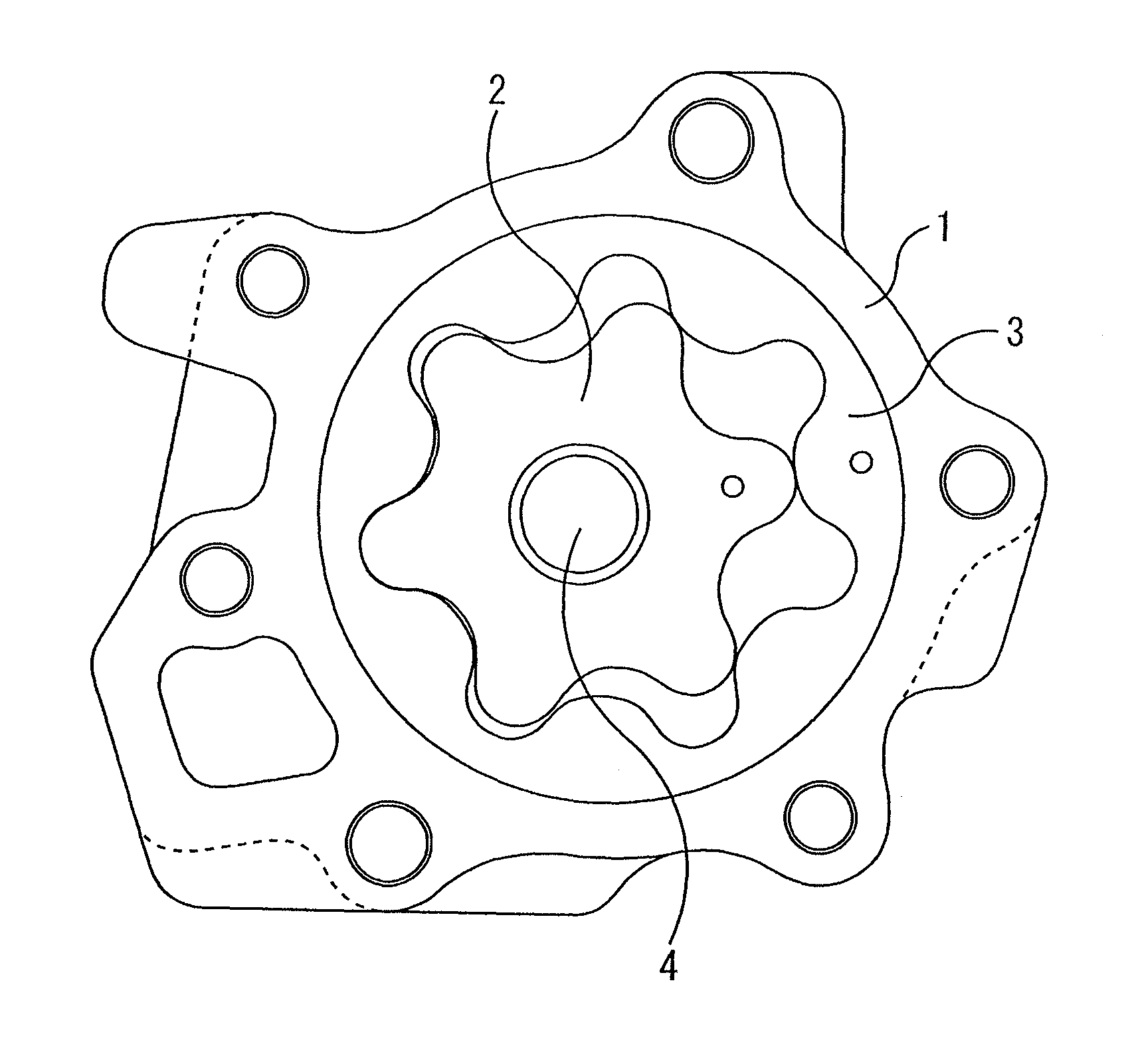
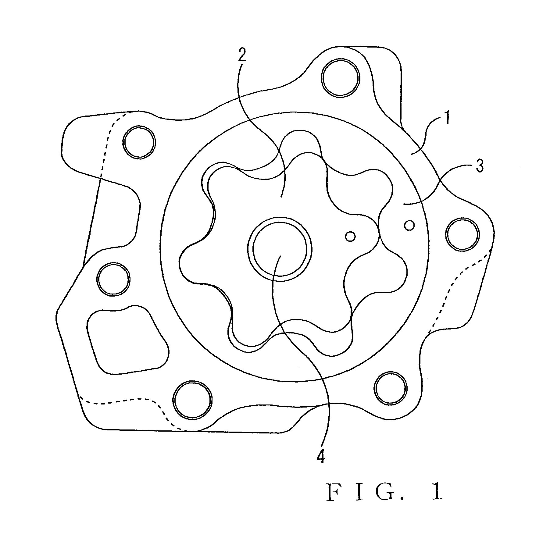
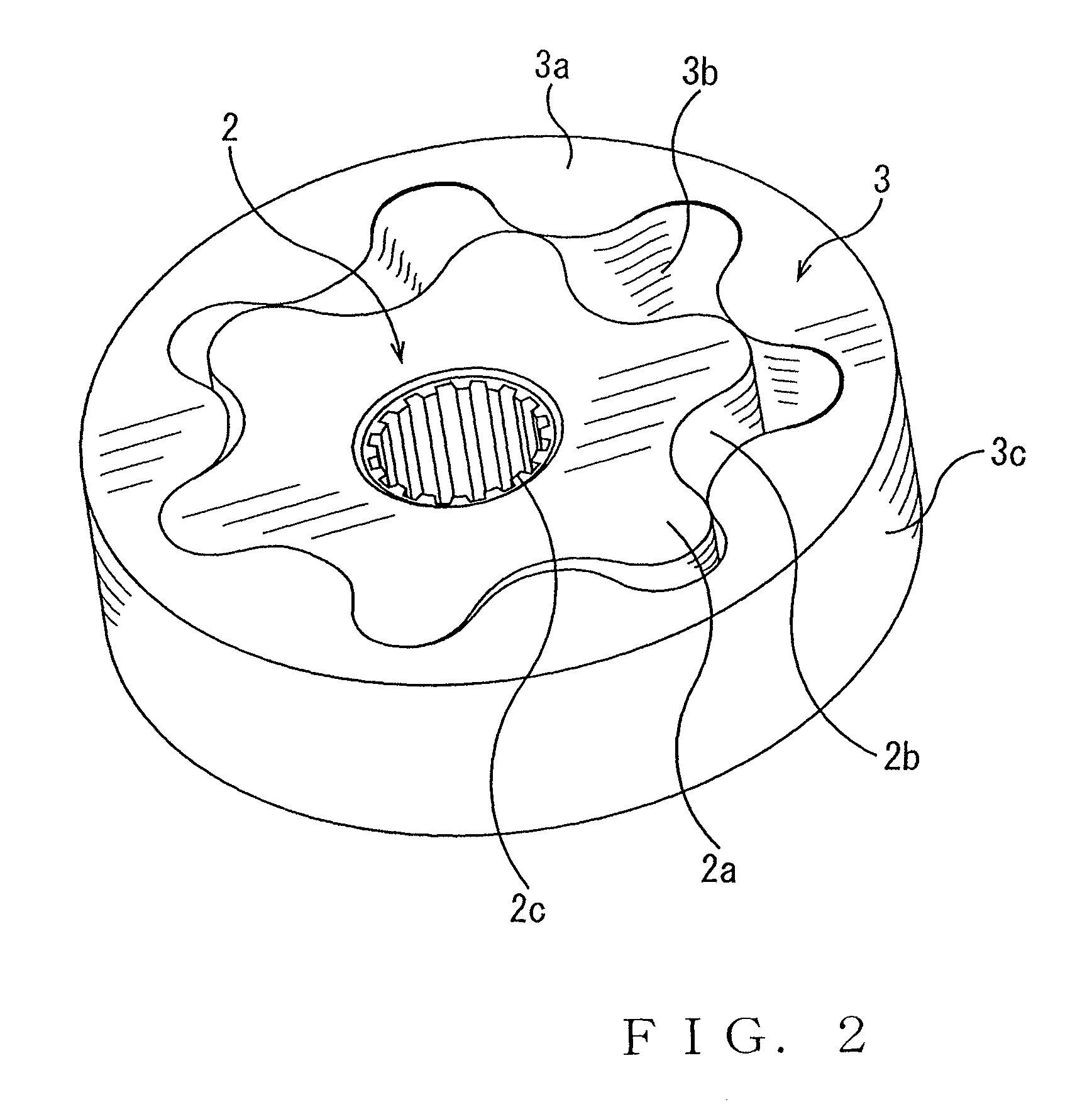
[0010]Referring to FIG. 1, a gerotor pump includes an inner rotor (driving rotor) 2 and an outer rotor (driven rotor) 3 that are housed in an oil pump body 1. As conventionally known, the inner rotor 2 has outer teeth in an appropriate number “n” on its outer periphery, a drive shaft 4 is joined with an inner periphery of the inner rotor 2 with a spline, a claw, and so on, the outer rotor 3 has inner teeth in a larger number “n+1” than “n” on its inner periphery, and the outer teeth and the inner teeth are meshed in such an arrangement that the outer rotor 3 is off-center from the center of the inner rotor 2 and incorporated in the oil pump body 1. In an oil pump for an automatic transmission, any shaft such as a transmission input shaft, that performs rotational motion, is used as the drive shaft 4.

[0011]As conventionally known, the inner rotor 2 is rotationally driven by rotation of the drive shaft 4, followed by rotation of the outer rotor 3, and the outer teeth of the inner roto...


PUM


Abstract

In a gear pump in which a driving rotor that is driven by a driving source meshes with a driven rotor that is driven by the driving rotor for rotation to pump a hydraulic oil, only one of the driving rotor and the driven rotor is given the steam treatment while the other remains untreated.

Description

CROSS-REFERENCED TO RELATED APPLICATION[0001]This application is a National Stage entry of International Application PCT / JP2010 / 072146, filed Dec. 9, 2010, which claims priority to Japanese Patent Application No. 2009-284481, filed Dec. 15, 2009, each of the disclosures of the prior applications being hereby incorporated in their entirety by reference.TECHNICAL FIELD[0002]The present invention relates to a gear pump that is used as an automotive oil pump and so on, and particularly to a technology of surface treatment on the rotor contacting surface of the gear pump.BACKGROUND ART[0003]Patent Document 1 below discloses that, in a gerotor pump, contacting surfaces of both of an inner rotor and an outer rotor are given a surface treatment to be coated with a carbide or nitride film to improve abrasion resistance. Also, as a treatment of the contacting surfaces of both of the inner rotor and the outer rotor, a steam treatment has conventionally been known. Meanwhile, Patent Document 2 ...

Claims


Application Information

Patent Timeline
Patent Type & Authority Patents(United States)
IPC IPC(8): F04C2/00F04C2/10
CPCF04C2/102F04C2230/41F04C2230/92F04C2270/16F05C2251/10
Inventor NIRASAWA, HIDEOKANEHARA, SHIGERUHIRAI, SHINICHIYAMANE, KOSUKESHINOHARA, MASAHIKO
Owner HONDA MOTOR CO LTD
Why Eureka
Eureka Blog
Learn More