System and processor implemented method for improved image quality and generating an image of a target illuminated by quantum particles

a technology of image quality and image generation, applied in the field of system and processor implemented method of improving image quality and generating image of target illuminated by quantum particles, can solve problems such as poor image, and achieve the effect of improving image generation

Inactive Publication Date: 2015-09-08
ARMY US SEC THE THE
View PDF21 Cites 11 Cited by
  • Summary
  • Abstract
  • Description
  • Claims
  • Application Information

AI Technical Summary

Benefits of technology

[0008]The frames of a region of interest are readily influenced by the effects of turbulence, obscuration, low signal to noise ratio, bad or changing weather and / or low-lighting conditions. This leads to a poor image. Yet, by employing the novel image improvement method of the present invention, the image can be significantly improved ameliorating these negative effects. Unlike classical image improvement techniques conventionally-employed, the novel processing relies upon quantum properties.
[0016]Additional refinements of the image improvement method may further be employed in many embodiments. These may comprise interpolating the pixel values for each frame to a finer resolution. Also, filtering of the frame data, the normalized pixel intensity value, and / or any data used in one or more calculations thereof, can be utilized to additional improve the generation of the image.

Problems solved by technology

This leads to a poor image.

Method used


Image

  • System and processor implemented method for improved image quality and generating an image of a target illuminated by quantum particles
  • System and processor implemented method for improved image quality and generating an image of a target illuminated by quantum particles
  • System and processor implemented method for improved image quality and generating an image of a target illuminated by quantum particles

Examples


embodiment 100

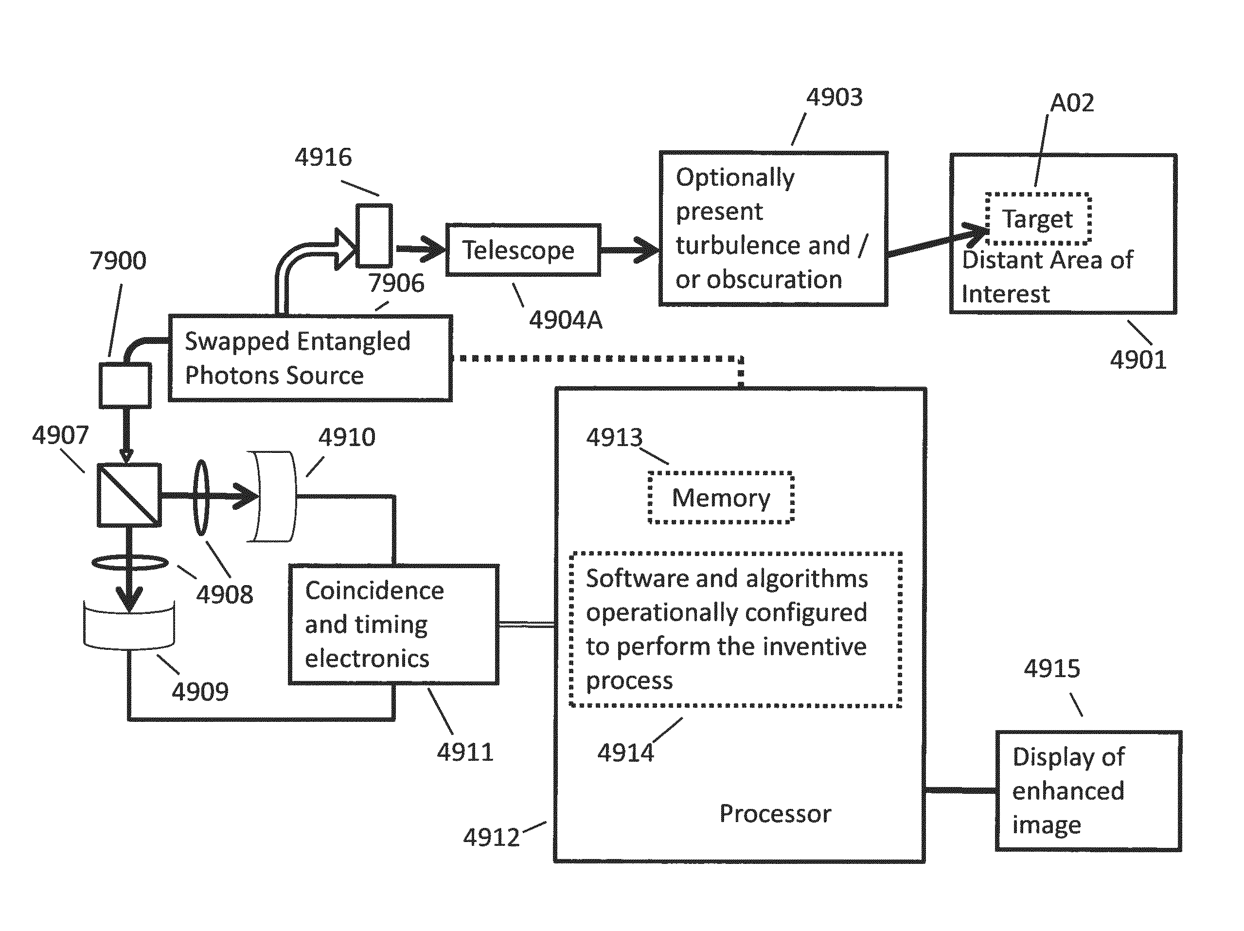
[0170]FIG. 19A illustrates a diagram of alternate preferred embodiment 100, that generates enhanced averaged second-order images or movies of a region of interest. Note, the region of interest may emit photons that are not reflected or scattered photons from some other photon source. A photon source (labeled source) may include, for example, the sun, moon, coherent, incoherent, or partially coherent light, entangled photons, infrared radiation emitted by atoms and molecules, accelerating charges, lasers, light bulbs, light emitting diodes (LEDs), chaotic laser light, pseudo-thermal light generated by passing laser light through a rotating ground glass or other scattering material, stars, moons, clouds, planets, space objects, fluorescent lamps, electrical discharges, plasmas, bio-luminescence, and stimulated emission. The distant target scene 101 comprises a target 102 which is an area used of the distant target scene for the particular region of interest developed for image testing...

case 1

[0226] As an example assume that an ensemble of measurements is made at location (a) and location (b). For this case assume that the ensemble consists of two measurement realizations 1 and 2. For realization 1, Ia(1)=8 and Ib (1)=8. For realization 2, Ia(2)=2 and Ib(2)=2. G(2)=aIb>−a>b>, where indicates and average over the ensemble of realizations. For this ensemble, G(2)=34−25=9. Examining Ia and Ib it is easy to see that the values of both of the measurements decrease at the same and typically referred to as correlated.

case 2

[0227] In a case where the ensemble of measurements is made at location (a) and location (b) for realizations 1 and 2, Ia(1)=2, Ia(1)=8 and Ib(1)=8, Ib(2)=2. Then G(2)=16−25=−9. In this example Ia increases in magnitude from 2 to 8 while Ib decreases from 8 to 2. This is typically referred to as anti-correlated.

Multiple Buckets on Same Image

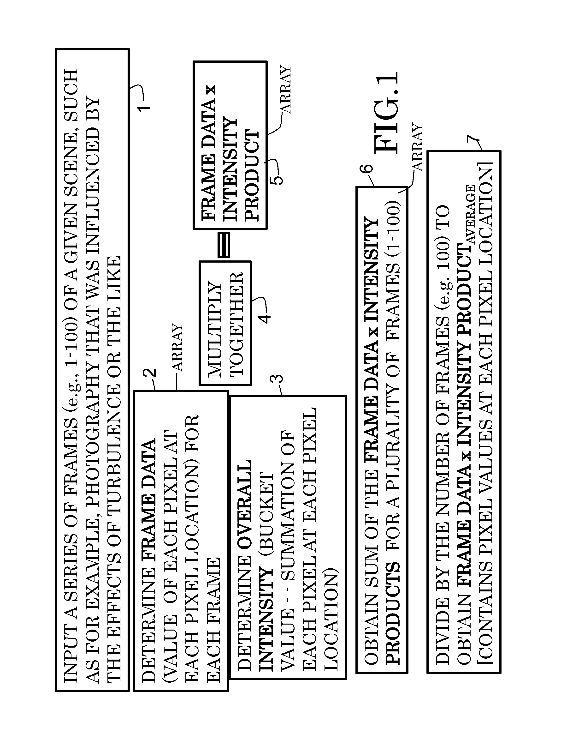
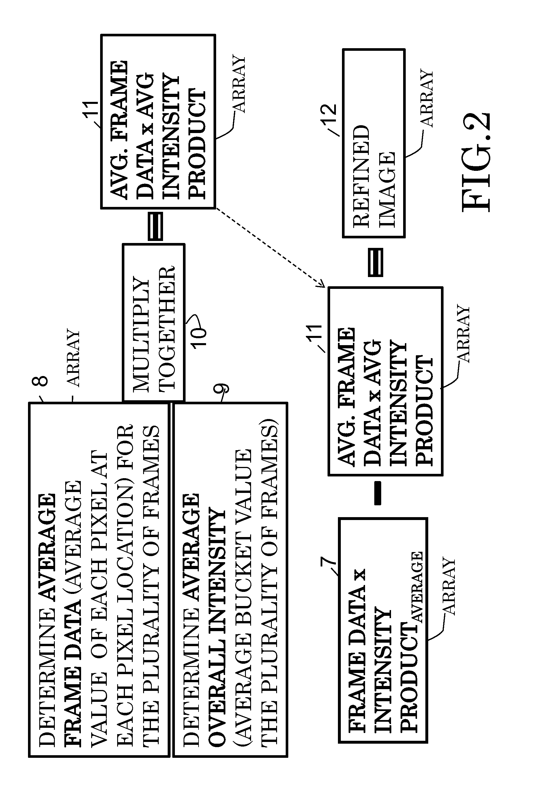
[0228]Bucket pixels can be allocated down to an individual pixel or a group of pixels in particular frames. The pixels in a group of pixel selected to be summed to a bucket (integrated intensities) value for a frame need not be contiguous. The bucket pixel or pixels may also be chosen on a per-frame basis. For instance, all pixels within 10% of the maximum pixel value for a frame may be chosen to be summed over for the bucket value for that frame. The spatial distribution of those pixels within 10% of the maximum pixel value is likely to change from frame to frame based on lighting conditions and turbulence / obscuration effects between the target ...


PUM


Abstract

According to some embodiments, system and methods for image improvement comprise: receiving a plurality of frames of a given region of interest, the frames comprised of a plurality of pixels; determining, based on a quantum property of the frames, a normalized pixel intensity value for each pixel of each of the plurality of frames; and generating an improved image of the given region of interest based on the plurality of frames and the corresponding normalized pixel intensity values for the frames, the order of the image being two. Also embodiments for generating an image of a target illuminated by quantum entangled particles, such as, photons, are disclosed.

Description

CROSS REFERENCE TO RELATED APPLICATIONS[0001]This application is a continuation-in-part (CIP) application of and claims priority to U.S. patent application Ser. Nos. 14 / 086,463 and 14 / 022,148, filed Nov. 21, 2013 and Sep. 9, 2013, respectively, both herein incorporated by reference in their entirety. Those applications, in turn, are a continuation-in-part (CIP) application of and claim priority to U.S. patent application Ser. No. 13 / 838,249, filed Mar. 15, 2013, now U.S. Pat. No. 8,594,455 and U.S. patent application Ser. No. 13 / 247,470 filed Sep. 28, 2011, now U.S. Pat. No. 8,532,427, herein incorporated by reference in their entirety. This application also claims priority to U.S. Provisional Application No. 61 / 834,497, titled “System and Method for Image Enhancement and Improvement,” filed on Jun. 13, 2013, herein incorporated by reference.GOVERNMENT INTEREST[0002]The invention described herein may be manufactured, used, and / or licensed by or for the United States Government witho...

Claims


Application Information

Patent Timeline
Patent Type & Authority Patents(United States)
IPC IPC(8): G06K9/00G06K9/40H04N5/225G06T5/00G06T5/50H04N5/21
CPCH04N5/211G06K9/40G06T5/005G06T5/007G06T5/008G06T5/50H04N5/2256G06T2207/10004G06T2207/10024G06T2207/10032G06T2207/20216G06T2207/20224H04N23/56
Inventor MEYERS, RONALD E.DEACON, KEITH S.
Owner ARMY US SEC THE THE
Why Eureka
Try Eureka