Plug unit and connection system for connecting capillary tubes, especially for high-performance liquid chromatography

a technology of capillary tubes and plug units, which is applied in fluid pressure sealing joints, component separation, instruments, etc., can solve the problems of undesired deformation, no longer being able to easily slip sealing elements onto the capillary tubes in the axial direction, and generating disadvantageous volum

Active Publication Date: 2015-09-15
DIONEX SOFTRON
View PDF20 Cites 10 Cited by
  • Summary
  • Abstract
  • Description
  • Claims
  • Application Information

AI Technical Summary

Benefits of technology

[0014]The invention provides a plug unit for connecting capillary tubes, especially for high-performance liquid chromatography, which can be used in a simple way for capillary tubes with different outer diameters in connection with bushing units with conventional diameters of receptacle openings. In addition, the present invention prevents the problem that, when the plug unit is removed, the sealing element detaches from the capillary tube and remains in the bushing unit. In addition, the invention provides a connection system with such a plug unit.

Problems solved by technology

However, it is disadvantageous that the sealing position is not realized in the plane of the end surface perpendicular to the longitudinal axis of the capillary tube, but is instead offset rearward a certain distance from the end face in the axial direction.
In this way, a dead volume is produced that has a disadvantageous effect, especially in high-performance liquid chromatography.
Such a deformation is undesired, especially because the sealing element is connected to the capillary tube here with a positive interference fit and non-positive-interference-fit connection and the sealing element can no longer be slipped onto the capillary tube easily in the axial direction.
If the sealing connection is released and should such a plug element be screwed into another bushing unit, for example because a component of the chromatography system must be replaced, then a tight connection can indeed be produced, but due to tolerances or manufacture-dependent differences in the depth of the receptacle opening, it can no longer be guaranteed that the capillary tube will again apply a force with its end face onto the end face of the line to which it should connect.
If the receptacle opening of the bushing unit of the exchanged component is longer in the axial direction than the previously used component, then an undesired dead volume is created.
If the receptacle opening for the capillary tube in the exchanged component is shorter in the axial direction than the previously used component, then the capillary tube is actually deformed, possibly damaged, by the pressure of the threaded fastener, and a tight connection is no longer possible under some circumstances.
Here there is again the risk that the ferrule is “crimped tight” onto the capillary tube, especially when the sealing element is made from a metal, for example, stainless steel.
In addition, in this plug unit it is disadvantageous that a support element for the helical spring must be mounted on the capillary tube, wherein this support element makes the production of such a plug unit more complicated.
In addition to the already mentioned disadvantages, the known connection systems feature the disadvantage that the risk arises that the sealing element will remain in place in the relevant receptacle opening of the bushing unit when the plug unit is removed and the capillary tube is pulled out from the bushing unit.
This represents an additional expense, however, and increases the dead volume of a connection.

Method used


Image

  • Plug unit and connection system for connecting capillary tubes, especially for high-performance liquid chromatography
  • Plug unit and connection system for connecting capillary tubes, especially for high-performance liquid chromatography
  • Plug unit and connection system for connecting capillary tubes, especially for high-performance liquid chromatography

Examples


Embodiment Construction

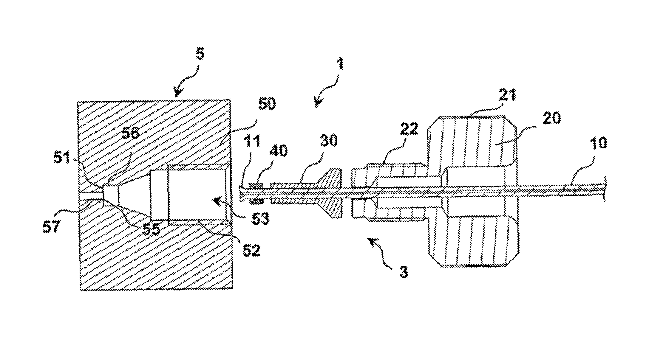
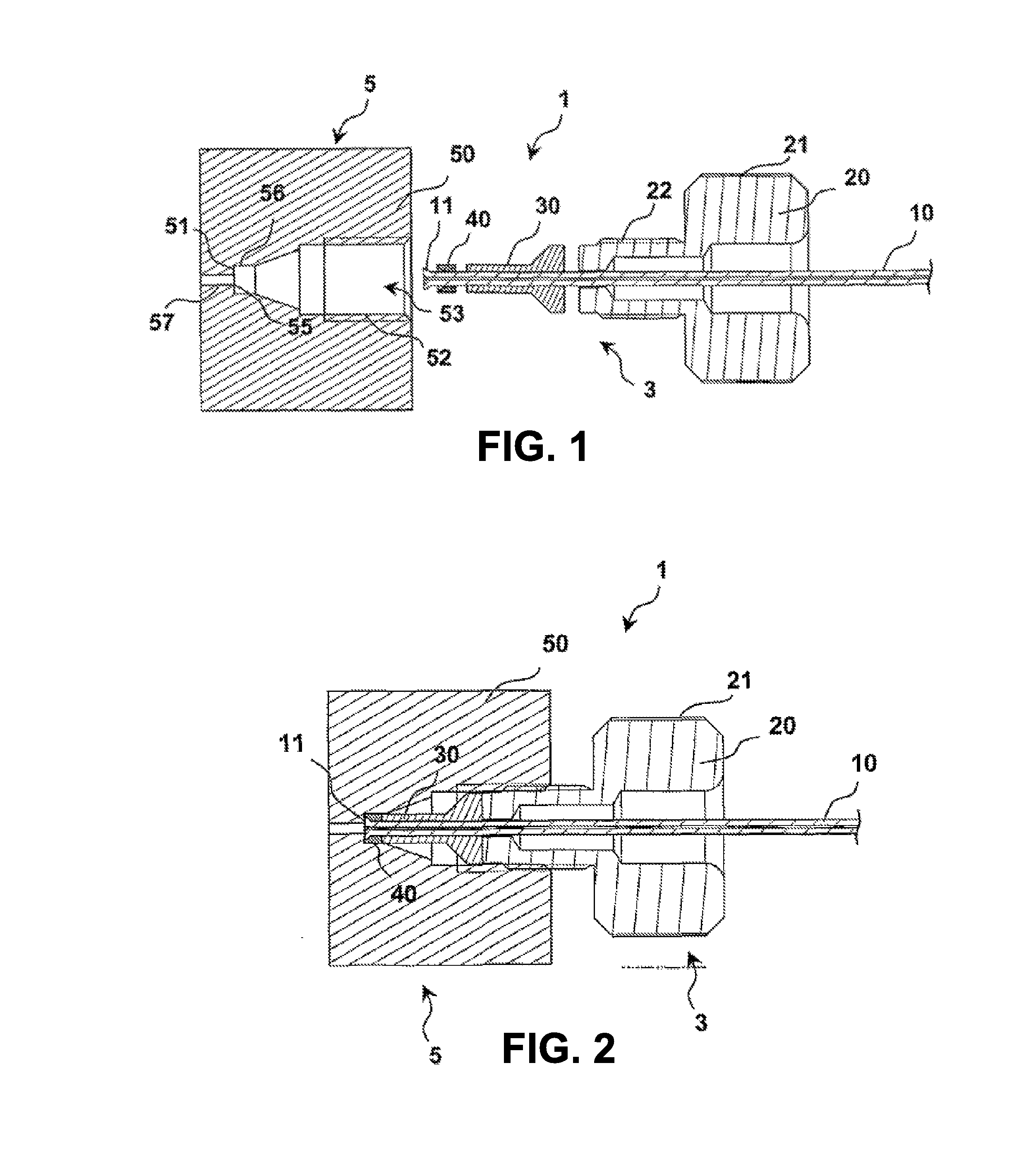
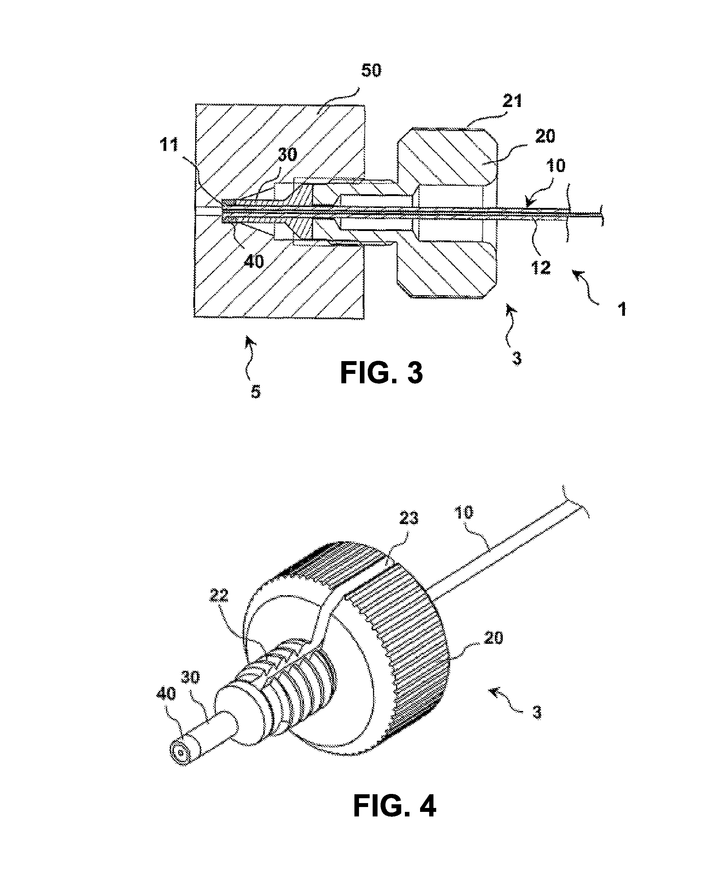
[0035]The connection system 1 shown in the disassembled state in FIG. 1 comprises a bushing unit 5, which is shown only schematically with respect to its outer contours that are not relevant to the invention, and which can be arranged, for example, on a component of a system for high-performance liquid chromatography, such as, for example, on a separating column. In addition, the connection system 1 comprises a plug unit 3. For its part, the plug unit 3 comprises, a plug capillary tube 10 that can be made, for example, from stainless steel, a plug housing 20 depicted in the form of a screw, a pressure piece 30 that, just like the plug housing 20, can be made from stainless steel or another metal, and a sealing element 40 that can be made, for example, from a material, such as, a suitable plastic, that can deform sufficiently elastically and / or plastically.

[0036]The screw-shaped plug housing 20 has a thickened head part that is provided with knurling 21 on the outer periphery and tha...


PUM

PropertyMeasurementUnit
pressuresaaaaaaaaaa
outer diameteraaaaaaaaaa
inner diameteraaaaaaaaaa

Abstract

A plug unit and system for connecting capillary tubes, especially for high-performance liquid chromatography, with a plug capillary tube projecting through a hole of a plug housing, which is detachably connectable to a bushing unit. The plug capillary tube front end projects into a capillary tube receptacle in the bushing unit with its end face essentially aligned opposite a front end of a bushing capillary tube or a bushing capillary passage opening of the bushing unit, the end face of which is butted against. The plug housing applies a force, with its end face facing the plug capillary tube end, directly or indirectly on an annular sealing element surrounding the plug capillary tube in the region of the front end of the plug capillary tube such that the front end of the plug capillary tube is sealed through deformation of the sealing element against the capillary tube receptacle opening.

Description

CROSS-REFERENCE TO RELATED APPLICATIONS[0001]This Application is a National Stage and claims the benefit under 35 U.S.C. 371 of International Application No. PCT / DE2009 / 001688, filed Nov. 27, 2009, which application claims priority to German Patent Application No. DE200810059897, filed Dec. 2, 2008.BACKGROUND OF THE INVENTION[0002]1. Technical Field of the Invention[0003]The invention relates to a plug unit for connecting capillary tubes, especially for high-performance liquid chromatography. In addition, the invention relates to a connection system consisting of a bushing unit and such a plug unit.[0004]2. Description of Related Art[0005]In chromatography systems, liquids or gases are fed through suitable connection lines between the components of the relevant system. These connection lines, which can be made, for example, from stainless steel, have suitable connection systems, also called fittings, available at their ends to enable creating a tight connection with the connectors o...

Claims


Application Information

Patent Timeline
Patent Type & Authority Patents(United States)
IPC IPC(8): F16L19/06G01N30/60
CPCG01N30/6026F16L19/061G01N30/6039G01N30/6091F16L21/04F16L21/035F16L19/00
Inventor HOCHGRAEBER, HERMANNSATZINGER, ADOLF
Owner DIONEX SOFTRON
Why Eureka
Try Eureka