A gas-coupled pulse tube refrigerator split-type cold-end heat exchanger and design method

A technology of pulse tube refrigerator and cold end heat exchanger, which is applied in the direction of gas circulation refrigerator, refrigerator, refrigeration and liquefaction, etc., which can solve the problems of pressure loss, reduce pressure loss, ensure uniformity, and prevent internal The effect of mixed flow

Active Publication Date: 2021-12-31
SHANGHAI INST OF TECHNICAL PHYSICS - CHINESE ACAD OF SCI
View PDF5 Cites 0 Cited by
  • Summary
  • Abstract
  • Description
  • Claims
  • Application Information

AI Technical Summary

Problems solved by technology

For coaxial and U-shaped cold fingers, there is also pressure loss caused by the gas working fluid flow direction being reversed by 180°, which requires a coherent and compact flow channel structure to reduce void volume and flow loss
[0009] At present, the cold-end heat exchanger of the conventional gas-coupled pulse tube refrigerator is far from meeting these requirements, and there are still large gaps in related technologies.

Method used


Image

  • A gas-coupled pulse tube refrigerator split-type cold-end heat exchanger and design method
  • A gas-coupled pulse tube refrigerator split-type cold-end heat exchanger and design method
  • A gas-coupled pulse tube refrigerator split-type cold-end heat exchanger and design method

Examples


Embodiment Construction

[0026] Below in conjunction with accompanying drawing and embodiment the specific embodiment of the present invention is described in further detail:

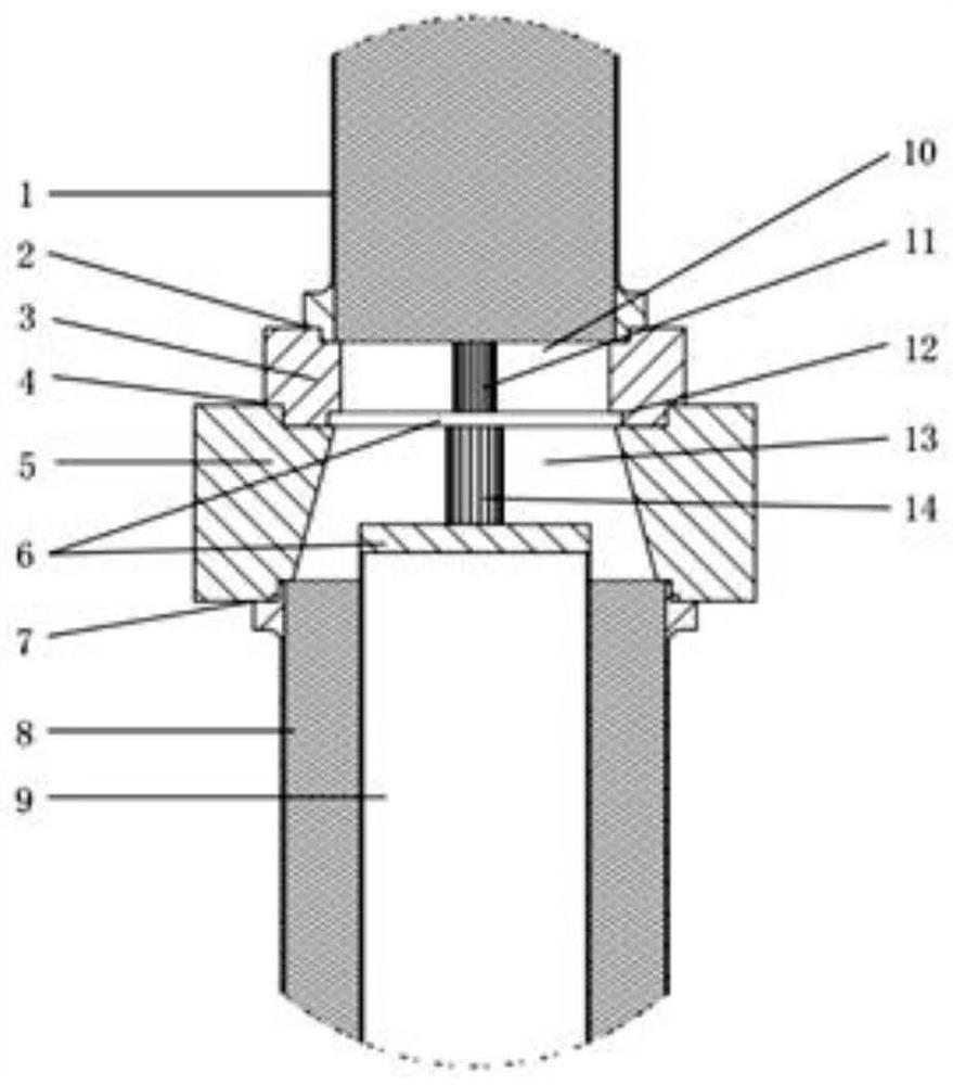
[0027] image 3 It is a partial cross-sectional view of a multi-stage pulse tube using the invented air-coupled pulse tube refrigerator split-type cold-end heat exchanger; Figure 4 It is the overall schematic diagram of the invented air-coupled pulse tube refrigerator split-type cold-end heat exchanger, wherein (1) is a top view, (2) is a bottom view, and (3) is a sectional view; Figure 5 It is a schematic diagram of the T-shaped through hole 14, wherein (1) is a plan view, and (2) is a cross-sectional view.

[0028] The air-coupled pulse tube refrigerator split cold end heat exchanger invented consists of an upper heat exchanger shell 3, a lower heat exchanger shell 5, a rectangular slit body 10, a through hole 11, a laminar flow element 6, a tapered narrow Composed of slit body 10 and T-shaped through hole 14, it is chara...


PUM


Abstract

The invention discloses a design method for a split-flow cold end heat exchanger of a gas-coupled pulse tube refrigerator, which comprises an upper heat exchanger shell, a lower heat exchanger shell, a rectangular slit body, a through hole, a laminar flow element, a conical Slit body, T-shaped through hole. Laminar flow elements are tightly filled in the cylindrical gap between the upper heat exchanger shell and the lower heat exchanger shell, and the upper and lower heat exchanger shells are connected by welding to realize the first stage cold storage, the first stage pulse tube and the second stage Connection of secondary cold storage. While maintaining the high-efficiency heat exchange advantages of the traditional heat exchanger, the invention realizes the natural diversion of the gas working medium, suppresses the turbulent disturbance of the gas in the heat exchange channel, and ensures the uniformity of the gas flow. The invention will significantly improve the overall performance of the refrigerator, and has very positive significance for realizing the compactness and practicality of the pulse tube refrigerator.

Description

technical field [0001] The invention belongs to the field of refrigeration and low temperature engineering, and relates to a pulse tube refrigerator, in particular to a gas-coupled pulse tube refrigerator shunt heat exchanger and a design method. Background technique [0002] The pulse tube refrigerator is a major innovation of the regenerative cryogenic refrigerator. It cancels the moving parts of the conventional regenerative refrigerator in the low temperature area, and has the advantages of high reliability, small mechanical vibration, long working life, high refrigeration efficiency, With outstanding advantages such as low electromagnetic noise, it is recognized as a new generation of long-life regenerative cryogenic refrigerators, and has been widely used in aerospace, low-temperature electronics, superconducting industry and low-temperature medical industry. [0003] In order to achieve a lower cooling temperature or facilitate cooling in multiple temperature zones, p...

Claims


Application Information

Patent Timeline
Patent Type & Authority Patents(China)
IPC IPC(8): F25B9/14
CPCF25B9/145F25B2309/1412
Inventor 党海政谭涵查睿
Owner SHANGHAI INST OF TECHNICAL PHYSICS - CHINESE ACAD OF SCI
Why Eureka
Try Eureka