
Multiscale digital rock modeling for reservoir simulation

a reservoir and digital technology, applied in the field of multi-scale digital rock modeling for reservoir simulation, can solve the problems of limited core and log control, complex and heterogeneous reserve rocks at all scales, and difficult preservation of essential geologic heterogeneity in the resulting coarse models

Active Publication Date: 2015-09-15
SCHLUMBERGER TECH CORP
View PDF21 Cites 13 Cited by
  • Summary
  • Abstract
  • Description
  • Claims
  • Application Information

AI Technical Summary

Benefits of technology

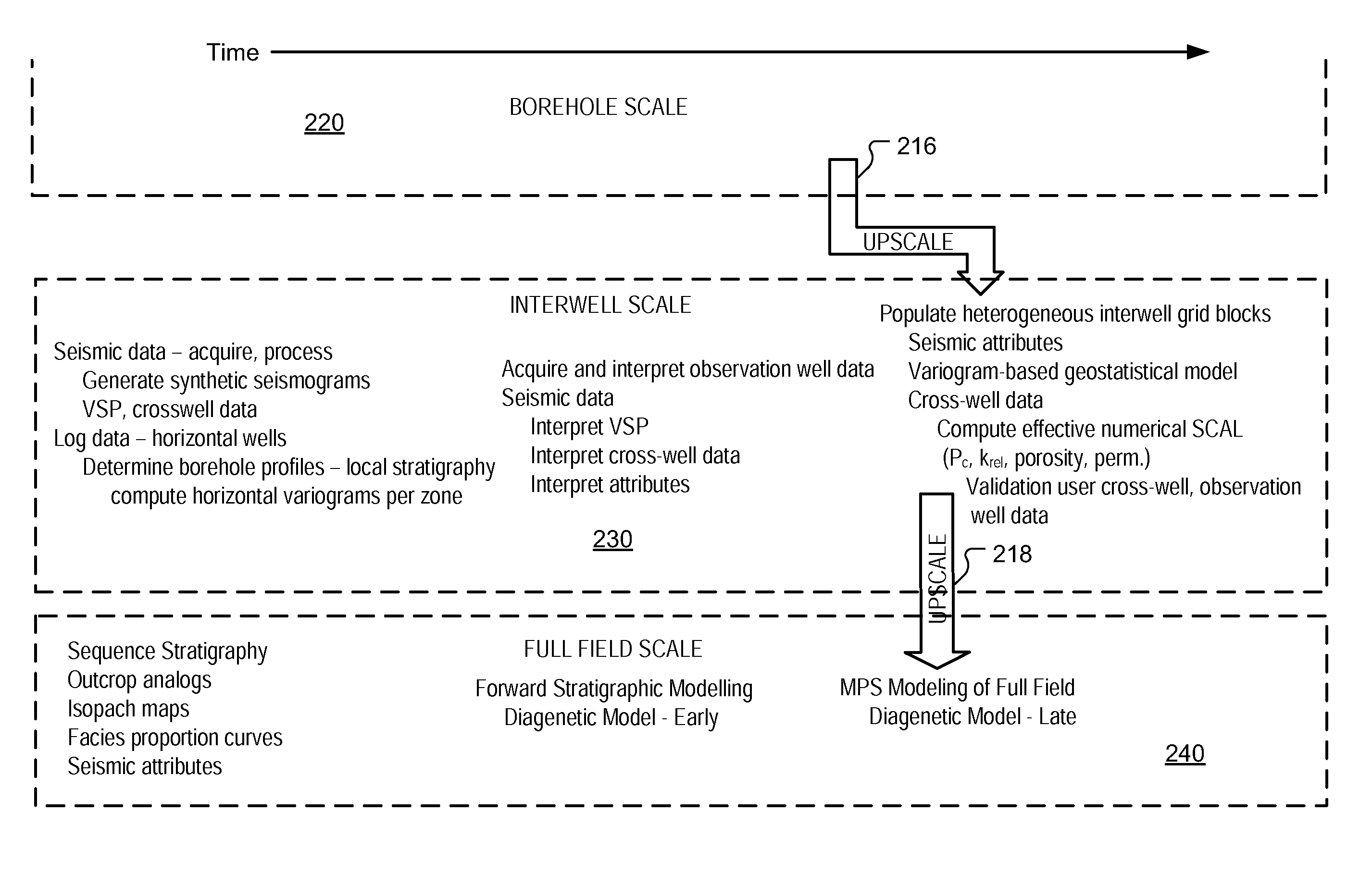
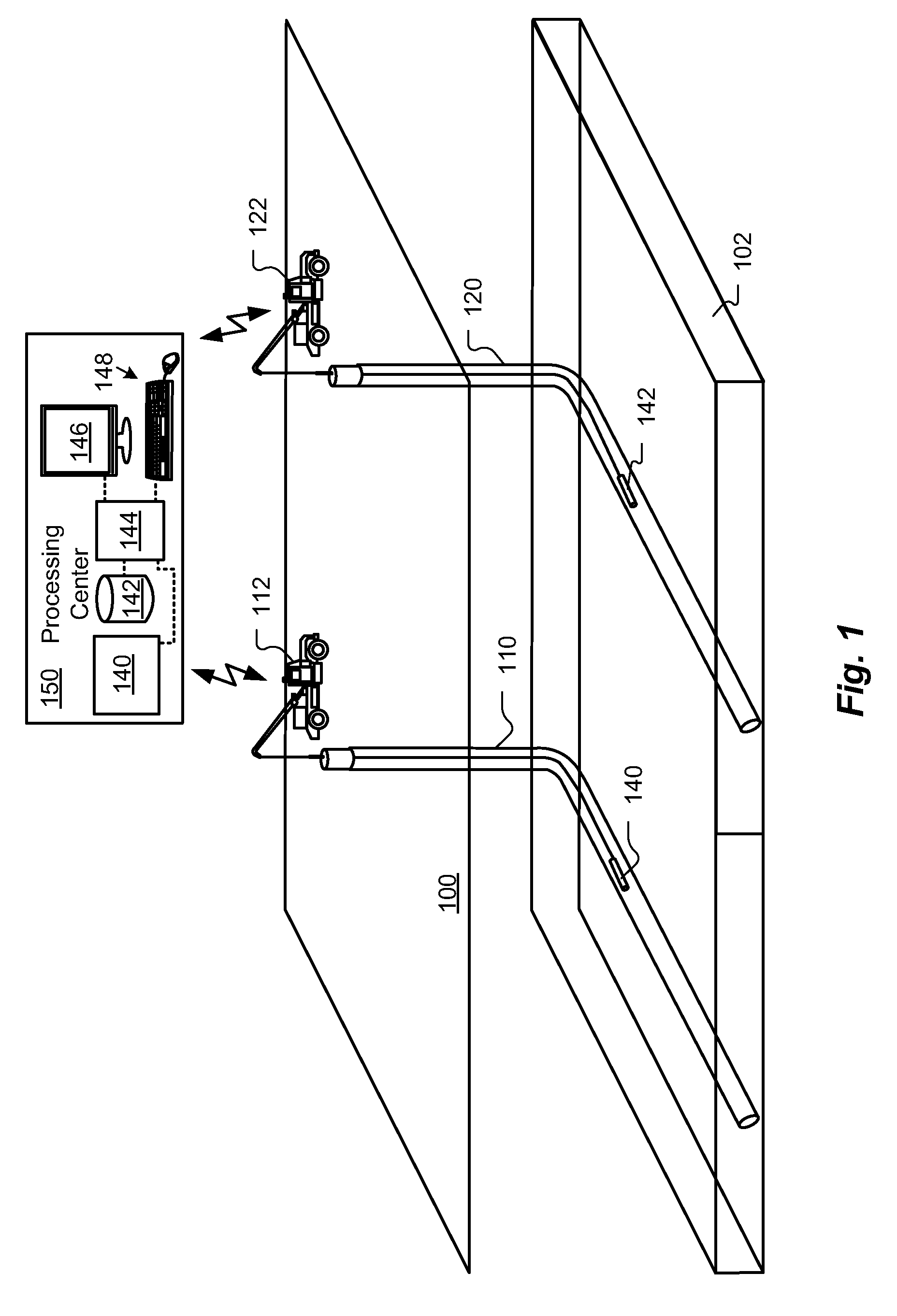
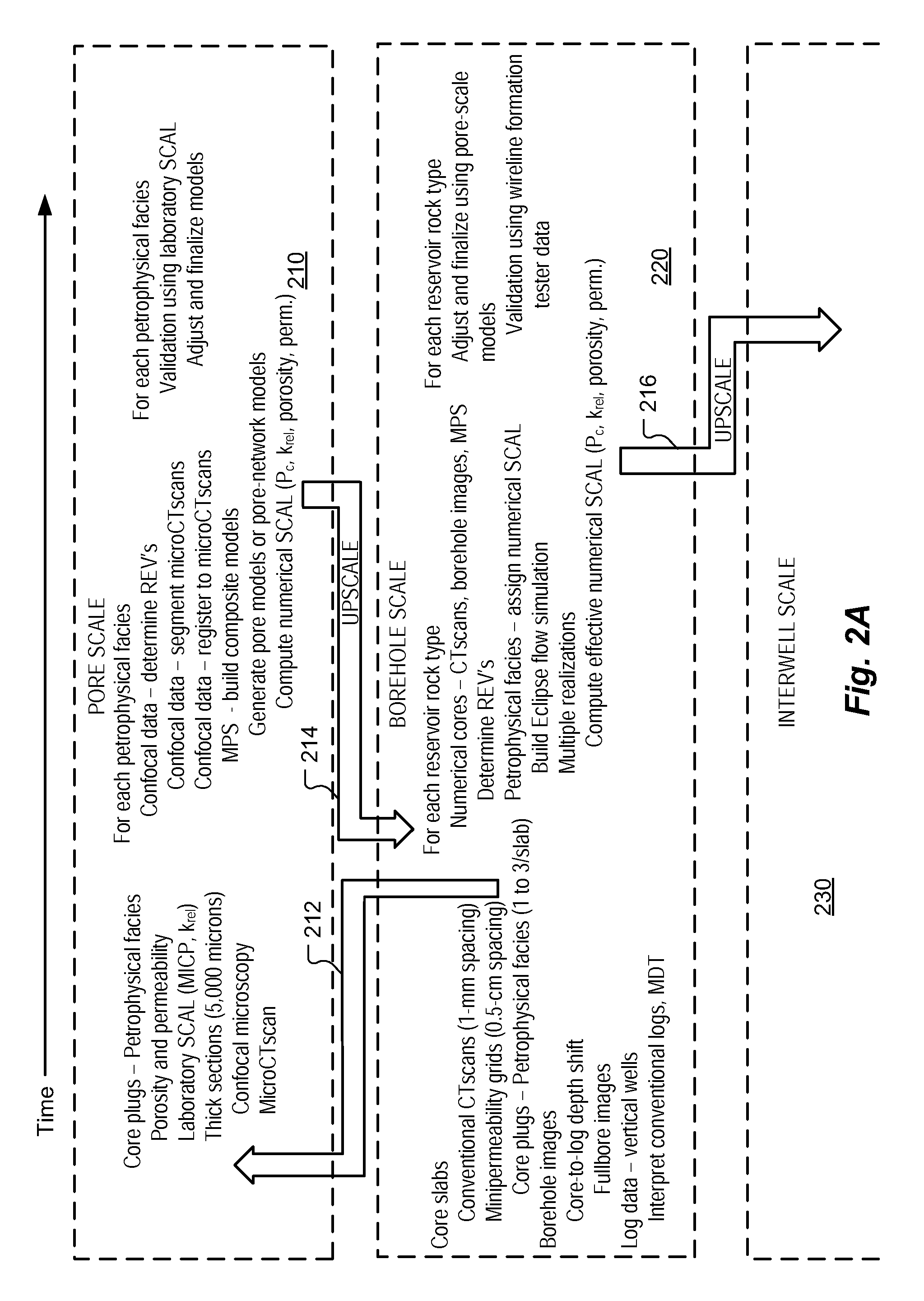
The patent text describes a method for upscaling digital rock modeling data to capture the characteristics of reservoir rock at a larger scale. This is done by combining data from smaller borehole-scale measurements with interwell-scale source data, which can include logs, cross-well geophysical measurements, and seismic data. The method uses computed values at a borehole-scale to determine porosity, permeability, capillary pressure, and other properties. The digital rock modeling data is generated using pore-scale data from CT scans and other techniques, and can be further upscaled to full-field-scale for more accurate modeling. Overall, the method allows for improved understanding of reservoir rock properties and the development of more accurate models for oil and gas production.

Problems solved by technology

Reservoir rocks are complex and heterogeneous at all scales.
The biggest challenge in this type of upscaling occurs because it is commonly difficult to preserve essential geologic heterogeneities in the resulting coarse models.
Heterogeneity causes problems in formation evaluation and reservoir simulation because reservoirs occupy enormous volumes, but there is limited core and log control.
Upscaling is necessary because reservoir simulators cannot handle the large number of cells in typical geocellular models.
Because of this assumption, their model does not capture rock heterogeneity, and does not depict true 3D pore geometry.
However, because they used overlapping sub-volumes, they obtained questionable results.

Method used


Image

  • Multiscale digital rock modeling for reservoir simulation
  • Multiscale digital rock modeling for reservoir simulation
  • Multiscale digital rock modeling for reservoir simulation

Examples


Embodiment Construction

[0026]The following description provides exemplary embodiments only, and is not intended to limit the scope, applicability, or configuration of the disclosure. Rather, the following description of the exemplary embodiments will provide those skilled in the art with an enabling description for implementing one or more exemplary embodiments. It being understood that various changes may be made in the function and arrangement of elements without departing from the spirit and scope of the invention as set forth in the appended claims.

[0027]Specific details are given in the following description to provide a thorough understanding of the embodiments. However, it will be understood by one of ordinary skill in the art that the embodiments may be practiced without these specific details. For example, systems, processes, and other elements in the invention may be shown as components in block diagram form in order not to obscure the embodiments in unnecessary detail. In other instances, well-...


PUM


Abstract

Methods for upscaling digital rock modeling data are described. Core-plug samples for pore-scale modeling are chosen using whole-core mini-permeability grids and conventional CT scans. Pore models or pore-network models are used for flow modeling. Borehole-scale models use MPS (Multi-Point Statistics) to combine mini-permeability grids and conventional CTscans of whole core with electrical borehole images to create 3D numerical pseudocores for each RRT (Reservoir Rock Type). Effective SCAL properties computed from various MPS borehole-scale realizations or models are used to populate interwell-scale models for each RRT. Effective properties computed from flow simulations for interwell volumes are used to populate full-field scale models. At the full-field scale, outcrop analogs, sequence stratigraphy, forward stratigraphic models, diagenetic models, and basin-scale models are combined using MPS to improve flow simulations. At every stage, REVs (representative element volumes) are computed to be certain rock heterogeneities have been captured.

Description

Cross-Reference to Related Applications[0001]The subject matter of this patent specification relates to the subject matter of the following commonly assigned applications: U.S. patent application entitled “Method to build 3D digital models of porous media using transmitted laser scanning confocal mircoscopy and multi-point statistics”, Ser. No. 12 / 459,414, filed on Jul. 1, 2009, U.S. patent application entitled “Method to quantify discrete pore shapes, volumes, and surface areas using confocal profilometry”, Ser. No. 12 / 459,454, filed on Jul. 1, 2009, U.S. patent application entitled “Method for characterizing a geological formation traversed by a borehole”, Ser. No. 12 / 384,945, filed Apr. 10, 2009, U.S. patent application entitled “Method to generate numerical pseudocores using borehole images, digital rock samples, and multi-point statistics”, Ser. No. 12 / 384,721, filed Apr. 8, 2009, U.S. patent application entitled “Methods to build 3D digital models of porous media using a combi...

Claims


Application Information

Patent Timeline
Patent Type & Authority Patents(United States)
IPC IPC(8): G06G7/50G06G7/48G01V99/00G06F30/13
CPCG01V99/005G01V20/00
Inventor HURLEY, NEIL FRANCISZHAO, WEISHUZHANG, TUANFENG
Owner SCHLUMBERGER TECH CORP
Learn More