Power source connection circuit

a connection circuit and power source technology, applied in the direction of pulse technique, electronic switching, semiconductor devices, etc., to achieve the effect of preventing excessive power consumption

Active Publication Date: 2015-09-15
ASAHI KASEI ELECTRONICS CO LTD
View PDF12 Cites 8 Cited by
  • Summary
  • Abstract
  • Description
  • Claims
  • Application Information

AI Technical Summary

Benefits of technology

[0014]As described above, according to the power source connection circuit of the present invention, even when a switch having a low dielectric strength is employed, it is possible to prevent excessive power consumption when the switch between an input terminal and an output terminal is turned off, and also to discharge electric charges accumulated in a gate of the switch.

Problems solved by technology

In addition, since the switch may be destroyed when dirt or the like between the output terminal and the ground causes a short circuit and a gate-source voltage of the switch becomes an overvoltage, the power source connection circuit needs to discharge electric charges accumulated in the gate of the switch.

Method used


Image

  • Power source connection circuit
  • Power source connection circuit
  • Power source connection circuit

Examples


first embodiment

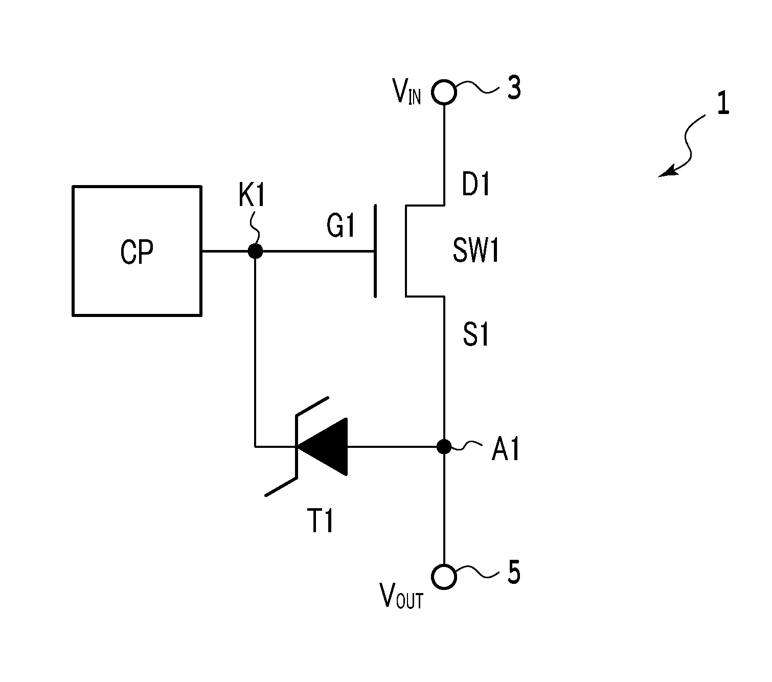
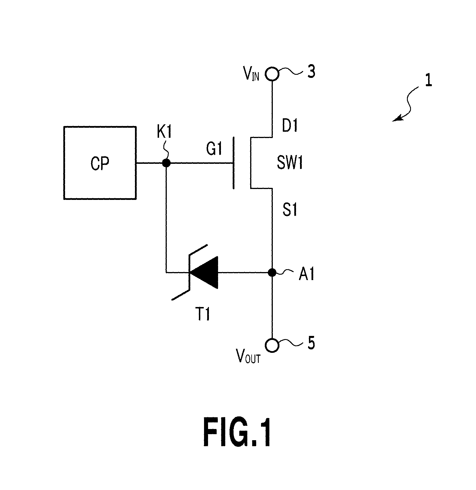
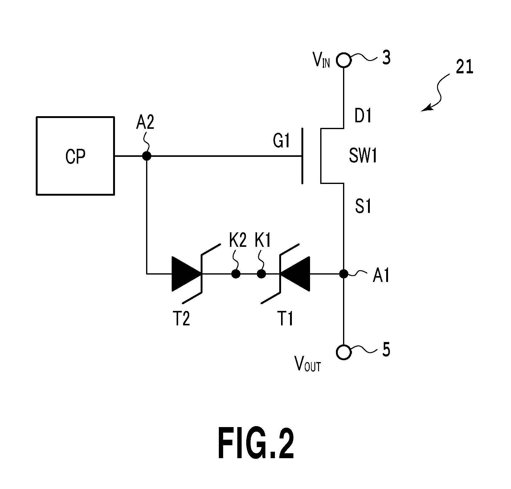
[0052]FIG. 6 is a circuit diagram of a power source connection circuit 61 according to a first embodiment of the present invention.

[0053]In FIG. 6, the power source connection circuit 61 includes a MOS switch SW1 for transmitting an input voltage VIN from an input terminal 3 to an output terminal 5 as an output voltage VOUT and a step-up circuit CP for supplying electric charges to a gate G1 of the MOS switch SW1. Further, the power source connection circuit 61 includes a rectifier unit 63 for discharging electric charges accumulated in the gate G1 to a ground terminal GND and a comparator CMP for comparing the output voltage VOUT with a reference voltage VREF. Still further, the power source connection circuit 61 includes a switch SW2 for causing electric charges to flow from the gate G1 to the ground terminal GND according to an output of the comparator CMP.

[0054]A drain D1 of the MOS switch SW1 is connected to the input terminal 3, a source S1 of the MOS switch SW1 is connected t...

second embodiment

[0065]FIG. 7 is a circuit diagram of a power source connection circuit 71 according to a second embodiment of the present invention. In FIG. 7, the power source connection circuit 71 includes a switch SW1 for transmitting an input voltage VIN from an input terminal 3 to an output terminal 5 as an output voltage VOUT and a step-up circuit CP for supplying electric charges to a gate G1 of the switch SW1. Further, the power source connection circuit 71 includes a Zener diode T7 for discharging electric charges accumulated in the gate G1 to a ground terminal GND and a comparator CMP for comparing the output voltage VOUT with a reference voltage VREF. Still further, the power source connection circuit 71 includes a switch SW2 for causing electric charges to flow from the gate G1 to the ground terminal GND according to an output of the comparator CMP. In the power source connection circuit 71 of the second embodiment, the rectifier unit 63 of the first embodiment includes one Zener diode ...

third embodiment

[0081]FIG. 8 is a circuit diagram of a power source connection circuit 81 according to a third embodiment of the present invention. In FIG. 8, the power source connection circuit 81 includes a switch SW1 for transmitting an input voltage VIN from an input terminal 3 to an output terminal 5 as an output voltage VOUT and a step-up circuit CP for supplying electric charges to a gate G1 of the switch SW1. Further, the power source connection circuit 81 includes diodes DI1 to DI3 for discharging electric charges accumulated in the gate G1 to a ground terminal GND and a comparator CMP for comparing the output voltage VOUT with a reference voltage VREF. Still further, the power source connection circuit 81 includes a switch SW2 for causing electric charges to flow from the gate G1 to the ground terminal GND according to an output of the comparator CMP. In the power source connection circuit 81 of the third embodiment, the rectifier unit 63 of the first embodiment includes one or more diode...


PUM


Abstract

There is provided a power source connection circuit, when a switch having a low dielectric strength is employed, capable of preventing excessive power consumption when the switch between an input terminal and an output terminal is turned off, and also discharging electric charges accumulated in a gate of the switch. A power source connection circuit includes a MOS switch connected to an output terminal; a step-up circuit for supplying electric charges to a gate of the MOS switch; an electric-charge discharging unit coupled between the gate and a ground terminal; and a comparator for comparing a voltage of the output terminal with a reference voltage, wherein the electric-charge discharging unit includes a rectifier unit coupled between the gate and the ground terminal, and a switch coupled in series with the rectifier unit between the gate and the ground terminal to receive an output signal of the comparator at a gate.

Description

TECHNICAL FIELD[0001]The present invention relates to a power source connection circuit, and more particularly to a power source connection circuit including a Zener diode and capable of discharging electric charges accumulated in a gate of a switch.BACKGROUND ART[0002]Nowadays, our living environment includes various kinds of electronic devices, such as a personal computer, a DVD player, and a video camera. Some of the electronic devices are connected to a power supply such as a battery or a wall outlet to operate, using a connection device such as a USB device. The connection device used in this case has a power source connection circuit for connecting an electronic device with a power supply.[0003]The power source connection circuit is provided with a switch between an input terminal to which a power supply is connected and an output terminal to which an electronic device is connected, so that when an input voltage is an overvoltage or when a current passing through the switch is...

Claims


Application Information

Patent Timeline
Patent Type & Authority Patents(United States)
IPC IPC(8): H03K17/687H03K17/06H03K17/081H03K17/08
CPCH03K17/08H03K17/063H03K17/08104H03K17/687H03K2217/0036H03K2217/0054
Inventor HAYASAKA, NAOTO
Owner ASAHI KASEI ELECTRONICS CO LTD
Why Eureka
Try Eureka