Method and apparatus for gasification of organic waste in batches

a gasification method and batch technology, applied in the direction of gasification process details, removal of gas contaminants, combustion process, etc., can solve the problems of limiting the disposal of waste into the sea, affecting the gasification effect of organic waste, so as to reduce the amount of process air, reduce the amount of synthesis gas produced, and prolong the effect of tim

Active Publication Date: 2015-09-22
PROTERRGO
View PDF75 Cites 8 Cited by
  • Summary
  • Abstract
  • Description
  • Claims
  • Application Information

AI Technical Summary

Benefits of technology

[0032]According to a second aspect of the invention, there is provided a reactor for gasification of organic waste in batch that generates a crude synthesis gas and is capable of sustaining the gasification on the synthesis gas produced.
[0058]The MAGS reactor does not use any refractory to insulate the walls. Consequently, the reactor has minimum thermal inertia and can be heated-up or cooled-down very quickly and the down time between processing cycles is minimized. A typical MAGS reactor, capable of treating 40 kilograms of waste per batch, will heat-up or cool-down in less than 15 minutes. The full processing cycle for a batch is about 120 minutes. Alternatively, an insulation for the system may be used. The insulation is based on wrapping a ceramic fibre blanket on the outside of the system (i.e. outside the outer walls of the primary and secondary gasifiers). In that case, the function of the insulation is primarily to protect an operator from the heat.

Problems solved by technology

However, many small communities live in isolation, as far as waste management is concerned (either due to geographic location or because of the nature of waste generated), and must treat their waste locally.
All of these options have serious problems associated with them.
The disposal of waste into the sea is restricted and the disposal of some waste, like plastic, is forbidden everywhere.
On-board storage of waste can cause serious health problems, infestations by rodents, may require large refrigerated containers, and many ports will not accept the waste or will charge high commissions for the final disposal.
Furthermore ships may be operating in coastlines of hostile countries, making the possible transfer of the waste to a port facility impossible.
Existing methods for on-board disposal (primarily incineration) are incapable of disposing of the waste without producing harmful or toxic emissions (such as dioxins arising from the combustion of plastics).
Landfill as a method of disposal is unacceptable (lack of biodegradation), shipping of the waste for treatment elsewhere involves exorbitant costs, and incineration in pits or small systems generates toxic emissions.
Many islands face similar problems; land is at a premium and therefore landfilling as well as shipment of the waste elsewhere are not attractive options.
Thus, there are very few small-scale options available today for treatment of waste in isolated habitats.
The systems that are available are either not compact and / or not environmentally safe, and require the use of significant amounts of externally provided energy.
It is not a process that is suitable for small scale waste treatment.
As such, pyrolysis is a viable process only for relatively large scale operations and for the treatment of specialty waste such as scrap tires and plastics.
Invariably, the system's complexity is increased in an effort to improve processing rate and energy efficiency.
All small-scale incinerators are characterized by numerous operating and environmental problems which make them not suitable for eliminating the waste of small isolated communities.
In fact, in the study completed for the World Health Organisation (WHO) by Batterman, S. entitled “Assessment of small-scale incinerators for health care waste”, from the Department of Environmental Health Sciences, University of Michigan, published in January 2004, it is concluded that no small-scale incinerator available today meets current environmental protection regulations.

Method used


Image

  • Method and apparatus for gasification of organic waste in batches
  • Method and apparatus for gasification of organic waste in batches
  • Method and apparatus for gasification of organic waste in batches

Examples


Embodiment Construction

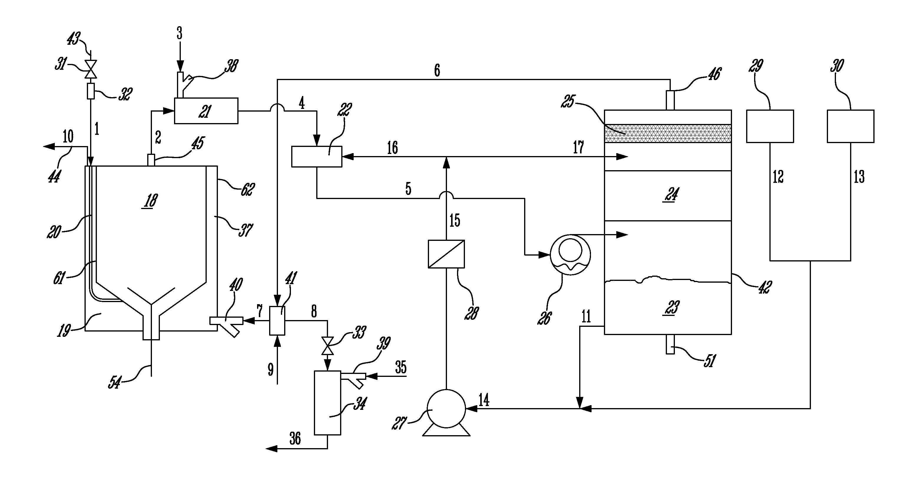
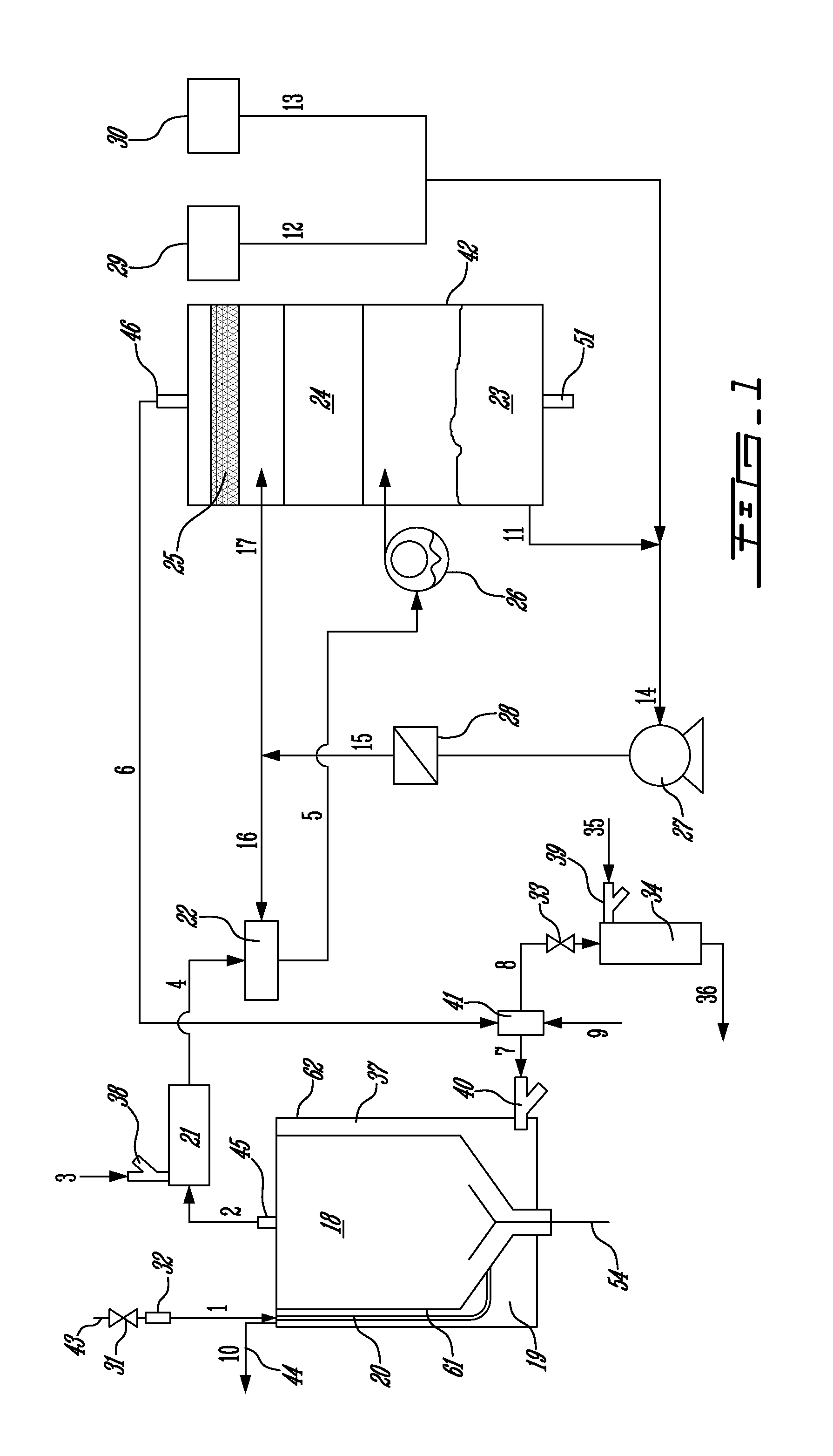
[0064]FIG. 1 shows a block diagram of one embodiment of the MAGS process as disclosed herein. A waste, without any prior pre-treatment, is placed into the primary gasification chamber 18 of the primary gasification reactor 37. A mixture 9 of fuel, such as propane and air, is fed through a combustible gas selector 41 into a dual-fuel burner 40 where it is burned in the primary combustion chamber 19 to start the gasification process. The process air 1 used for the gasification of the waste is fed through the passage 20 between the primary gasification chamber wall 61 and the primary combustion chamber wall 62. The gasification chamber 18 operates under negative pressure (approximately −10″ H2O) created by the use of a water ring pump 26, which pumps the crude synthesis gas 2 out of the gasification chamber 18. The process air 1 is allowed to be drawn into the primary gasification reactor 37 using the pressure difference between the pressure in the primary gasification chamber 18 and t...


PUM

PropertyMeasurementUnit
temperatureaaaaaaaaaa
temperaturesaaaaaaaaaa

Abstract

A gasification reactor for processing organic waste in batches comprises a primary gasification reactor (62) that includes a primary gasification chamber (18) and a surrounding combustion chamber (19), a secondary gasification chamber (21), a synthesis gas decontamination unit (42) and a combustible gas selector (41). The waste is loaded into the primary gasification chamber through a latched opening and heated from the combustion of a fuel in the combustion chamber (19) to convert the waste to a synthesis gas. The gasification chamber (18) has an intake (20) for introducing pre-heated process air (1) therein. The combustion chamber operates either with a conventional fuel (9) or with the produced synthesis gas (6). The secondary gasification chamber (21) thermally treats the synthesis gas (2) to eliminate tars. The decontamination unit (42) scrubs the synthesis gas of contaminants including particulates and acid gases. The clean synthesis gas (6) is directed to the combustible gas selector (41) which selectively feeds either the combustible fluid (9) or the synthesis gas (6) to the burner (40).

Description

FIELD OF THE INVENTION[0001]This invention relates to waste treatment and to gasification of organic material. More specifically, it relates to an improved method and apparatus for the gasification of organic waste in batches.BACKGROUND OF THE INVENTION[0002]For most people, waste management involves mostly taking the garbage out of their home where it is picked up by a municipal service and taken to an authorized large-scale waste processing facility. However, many small communities live in isolation, as far as waste management is concerned (either due to geographic location or because of the nature of waste generated), and must treat their waste locally. Small isolated communities can be found anywhere and may include military and commercial ships, research and military outposts, northern communities, small islands, resorts, clinics and hospitals, laboratories, industries and many others.[0003]A typical example of an isolated community is a ship at sea (for example a cargo ship or...

Claims


Application Information

Patent Timeline
Patent Type & Authority Patents(United States)
IPC IPC(8): F23B70/00B09B3/00B01J8/00C10J3/04C10J3/44C10J3/72C10K1/00C10K1/10C10K1/20C10K1/32
CPCC10J3/44C10J3/04C10J3/723C10K1/003C10K1/007C10K1/101C10K1/20C10K1/32C10J2300/1246C10J2300/0946C10J2300/1215Y02P20/129
Inventor TSANTRIZOS, PANAYOTIS
Owner PROTERRGO
Why Eureka
Try Eureka