

Cooling fan
a cooling fan and fan body technology, applied in the field of cooling fans, can solve the problems of increasing manufacturing costs, and achieve the effect of avoiding damage to the cooling fan and lowering the operation nois
- Summary
- Abstract
- Description
- Claims
- Application Information
AI Technical Summary
Benefits of technology
Problems solved by technology
Method used
Image

Examples
first embodiment
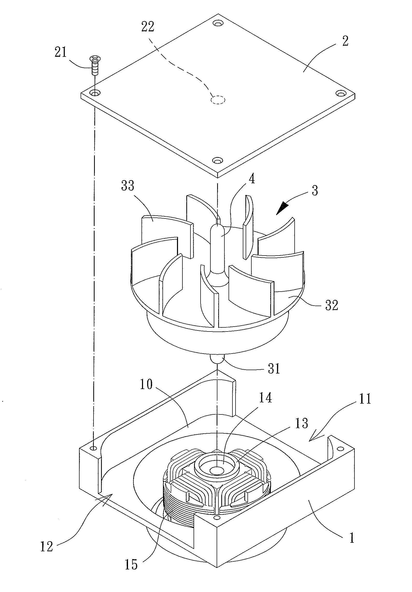
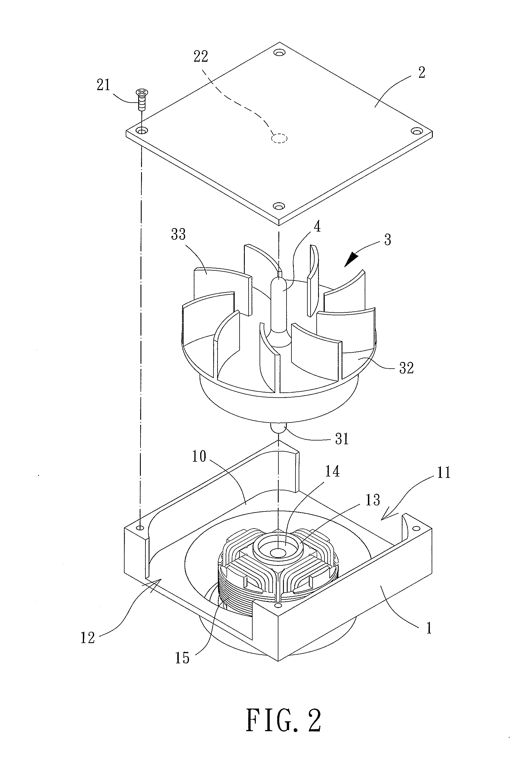
[0024]Referring to FIGS. 2 and 3, a cooling fan with a base 1, a lid 2, a fan wheel 3 and an auxiliary shaft assembly 4 is shown according to the invention. The base 1 is adapted to support the fan wheel 3. The lid 2 is arranged on a side of the fan wheel 3 opposite to the base 1 to protect the fan wheel 3. The fan wheel 3 is able to rotate relatively to the base 1 and the lid 2. The auxiliary shaft assembly 4 is disposed between the lid 2 and the fan wheel 3 to prevent the fan wheel 3 from touching the lid 2.
[0025]The base 1 has an air channel 10 forming at least one first opening 11 and at least one second opening 12. Specifically, if the present cooling fan is an axial fan, the at least one first opening 11 and at least one second opening 12 are formed on two axial sides of the base 1, with the two axial sides spaced in an axial direction of the fan wheel 3. If the present cooling fan is a centrifugal fan, the at least one first opening 11 and at least one second opening 12 are f...
second embodiment
[0030]Referring to FIG. 5, the cooling fan of the invention is shown. In this embodiment, the auxiliary shaft assembly 4 is in the form of a single rod integrally formed on the fan wheel 3, and is preferably made of the same material of the fan wheel 3 and formed on the top of the hub 32. Similarly, the second gap “G2” between the bottom face of the lid 2 and a free end of the signal rod serving as the auxiliary shaft assembly 4 is smaller than the first gap “G1” between the highest point “T” and the bottom face of the lid 2, or the predetermined length “L” is larger than the protruding height “H.” Accordingly, the highest point “T” of the fan wheel 3, such as top edges of the blades 33 of the fan wheel 3 in this embodiment, is surely prevented from touching the bottom of the lid 2.
[0031]Referring to FIG. 6, a third embodiment of the cooling fan of the invention is shown. In comparison with the elements of the first embodiment, the major difference between the third and first embodi...
fourth embodiment
[0032]Referring to FIG. 7, the cooling fan of the invention is shown. In this embodiment, the auxiliary shaft assembly 4 is in the form of a single rod integrally formed on the lid 2, and is preferably made of the same material of the lid 2 and formed on the bottom face of the lid 2. Besides, in this embodiment, a gap between the single rod serving as the auxiliary shaft assembly 4 and the hub 32 of the fan wheel 3 is defined as the second gap “G2”, since the single rod connects with the lid 2 and since there is no separation between the auxiliary shaft assembly 4 and the lid 2 in this embodiment. Similarly, the second gap “G2” between the auxiliary shaft assembly 4 and the fan wheel 3 is smaller than the first gap “G1” between the highest point “T” and the bottom face of the lid 2, or the predetermined length “L” is larger than the protruding height “H.” Therefore, it is impossible for the highest point “T” of the fan wheel 3, such as top edges of the blades 33 of the fan wheel 3 i...
PUM
 Abstract
Description
Claims
Application Information