Method and system using radiometric volumetric data for detecting oil covered by ice

a radiometric volumetric data and oil mass technology, applied in the field of oil resources, can solve the problems of difficult or impossible detection of oil slicks, complicated oil slick detection with airborne or satellite sensors of sar/slar, and insufficient energy level, and achieve accurate processing of radiometric volumetric data.

Active Publication Date: 2015-09-22
HARRIS CORP
View PDF14 Cites 2 Cited by
  • Summary
  • Abstract
  • Description
  • Claims
  • Application Information

AI Technical Summary

Benefits of technology

[0011]Multi-band radiometry advantageously takes advantage of energy differences in RF signatures of black-body radiations with respect to an oil mass and ice to reliably detect an oil mass covered by ice. The radiometric data collected at the different frequencies defines a combined x-y-depth profile that may advantageously provide a 3-dimensional visualization of the oil mass covered by the ice.
[0014]The collecting may include collecting the radiometric data over a predetermined dwell time for a given location. This advantageously allows a sufficient energy level to be received so at to more accurately process the radiometric volumetric data.

Problems solved by technology

Such pursuits often take place in harsh, offshore conditions.
During freeze-up and through much of the winter, long periods of darkness and multiple oil / ice scenarios add to the challenges of detection, mapping and tracking oil in ice.
However, detection of an oil mass covered by ice is much more difficult.
Moreover, during freeze-up in fall and early winter, any detection of oil among ice with SAR / SLAR airborne or satellite sensors may be complicated by the presence of grease ice.
The presence of grease or new ice in conjunction with an oil spill on the water will produce close to identical signatures in the radar imagery, making detection of an oil slick difficult or impossible.
While these other technologies may work when the oil is on or near the surface of the ice, they may not be very effective in detecting an oil mass covered by thick ice.

Method used


Image

  • Method and system using radiometric volumetric data for detecting oil covered by ice
  • Method and system using radiometric volumetric data for detecting oil covered by ice
  • Method and system using radiometric volumetric data for detecting oil covered by ice

Examples


Embodiment Construction

[0036]The present invention will now be described more fully hereinafter with reference to the accompanying drawings, in which preferred embodiments of the invention are shown. This invention may, however, be embodied in many different forms and should not be construed as limited to the embodiments set forth herein. Rather, these embodiments are provided so that this disclosure will be thorough and complete, and will fully convey the scope of the invention to those skilled in the art. Like numbers refer to like elements throughout, and prime notation is used to indicated similar elements in alternative embodiments.

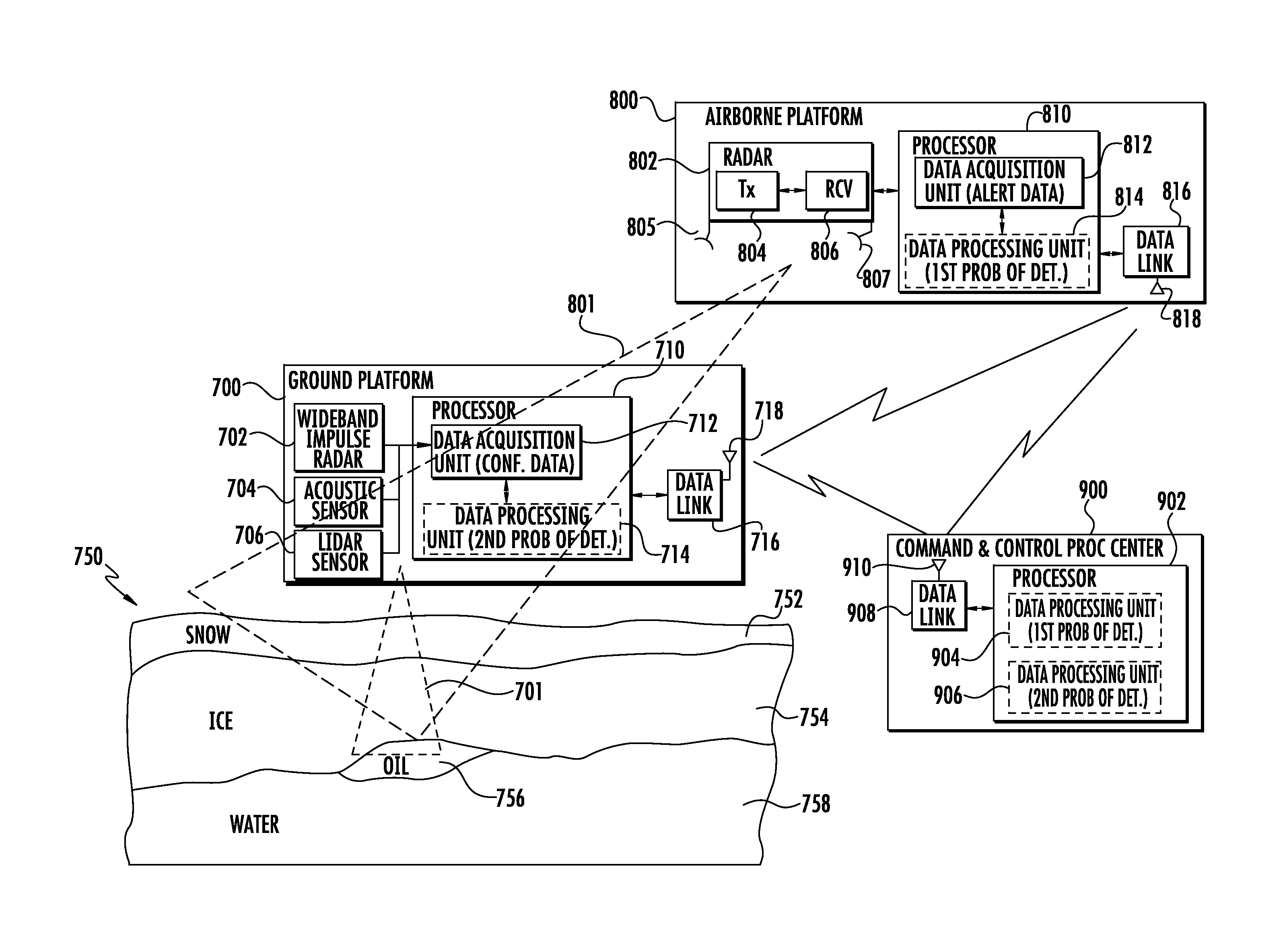
[0037]In Arctic regions, for example, a thickness of ice may vary from a few centimeters to 5 meters. The area to be searched when looking for a leaked oil mass is typically within a predetermined area associated with an oil extraction site or an oil pipeline site. The oil extraction site may be an oil platform within the Arctic waters, and the oil pipeline site may extend...


PUM


Abstract

A method for detecting an oil mass covered by ice includes collecting radiometric data different frequencies, corresponding to respective different depths into the ice, using at least one airborne platform moved about a search area above the ice so that the radiometric data defines radiometric volumetric data. The radiometric volumetric data is processed to thereby detect an oil mass covered by the ice.

Description

FIELD OF THE INVENTION[0001]The present invention relates to the field of oil resources, and more particularly, to a method and system for detecting an oil mass covered by ice.BACKGROUND OF THE INVENTION[0002]As the world's demand for fossil fuels increases, energy companies find themselves pursuing hydrocarbon resources in more remote areas of the world. Such pursuits often take place in harsh, offshore conditions. In recent years, drilling and production activities have been started in the Arctic regions.[0003]Spill detection and mapping may be particularly important for Arctic spills as oil may be hidden from view under snow and ice during periods of almost total darkness. Close to 24 hours of daylight in the spring and summer months facilitates monitoring oil spilled during the break-up and open water periods, but periods of fog and a low cloud ceiling remain as serious impediments. During freeze-up and through much of the winter, long periods of darkness and multiple oil / ice sc...

Claims


Application Information

Patent Timeline
Patent Type & Authority Patents(United States)
IPC IPC(8): G01S13/89G01V3/12G01V3/17
CPCG01S13/89G01V3/12G01V3/17
Inventor SHIPLEY, JOHN WARNERGANTHIER, EMILEHOGUE, STEPHEN TFREEMAN, SEANMEDLIN, GREGORYBEADLE, EDWARD
Owner HARRIS CORP
Why Eureka
Try Eureka