Fast transition running shoe

a fast transition and running shoe technology, applied in the direction of fastenings, uppers, bootlegs, etc., can solve the problem of obviating the factor

Inactive Publication Date: 2015-09-29
ARDELL DONALD B +1
View PDF30 Cites 28 Cited by
  • Summary
  • Abstract
  • Description
  • Claims
  • Application Information

AI Technical Summary

Benefits of technology

[0008]It is an objective of the present disclosure to eliminate the foregoing problems associated with the T2 transition.
[0009]One risk factor obviated by the unique design of the running shoe disclosed herein is that of cramping in the calves, quadriceps, hamstrings or back muscles. These occurrences are common after having engaged in the preceding extreme exertions of swimming and cycling prior to entering the T2 zone. Therefore, eliminating the need to bend during the process of transitioning to running shoes for the third and final triathlon segment is highly desirable.
[0010]More specifically, the disclosure relates to a running shoe with a closure system that enables a participant in a multi-sport event (e.g., triathlon or duathlon) to complete a transition from one phase (i.e., the bike segment) to another (i.e., the running segment) in the fastest possible manner. The running shoe eliminates the time delay normally incurred in the process of devoting 100 percent of attention to the act of foot insertion, that is, bending over to insert and adjust both feet into running shoes manually. The running shoe also eliminates the customary step of bending over to touch the shoe area, and adjusting and otherwise devoting energy and precious time to securing the shoe fastening system. The running shoe facilitates the insertion of both feet during, not after, the performance of the two essential transition activities, specifically securing the bicycle to a post and removing the bicycle helmet. The running shoe is thus unique in converting what has always been at least a three-step process in the biking to running so-called “T2 transition” into a time-saving two-step process by using a reclining and / or pivotable heel design and two related closure elements, none of which requires hand contact with the shoe area to secure the foot in the shoe.

Problems solved by technology

One risk factor obviated by the unique design of the running shoe disclosed herein is that of cramping in the calves, quadriceps, hamstrings or back muscles.

Method used


Image

  • Fast transition running shoe
  • Fast transition running shoe
  • Fast transition running shoe

Examples


first embodiment

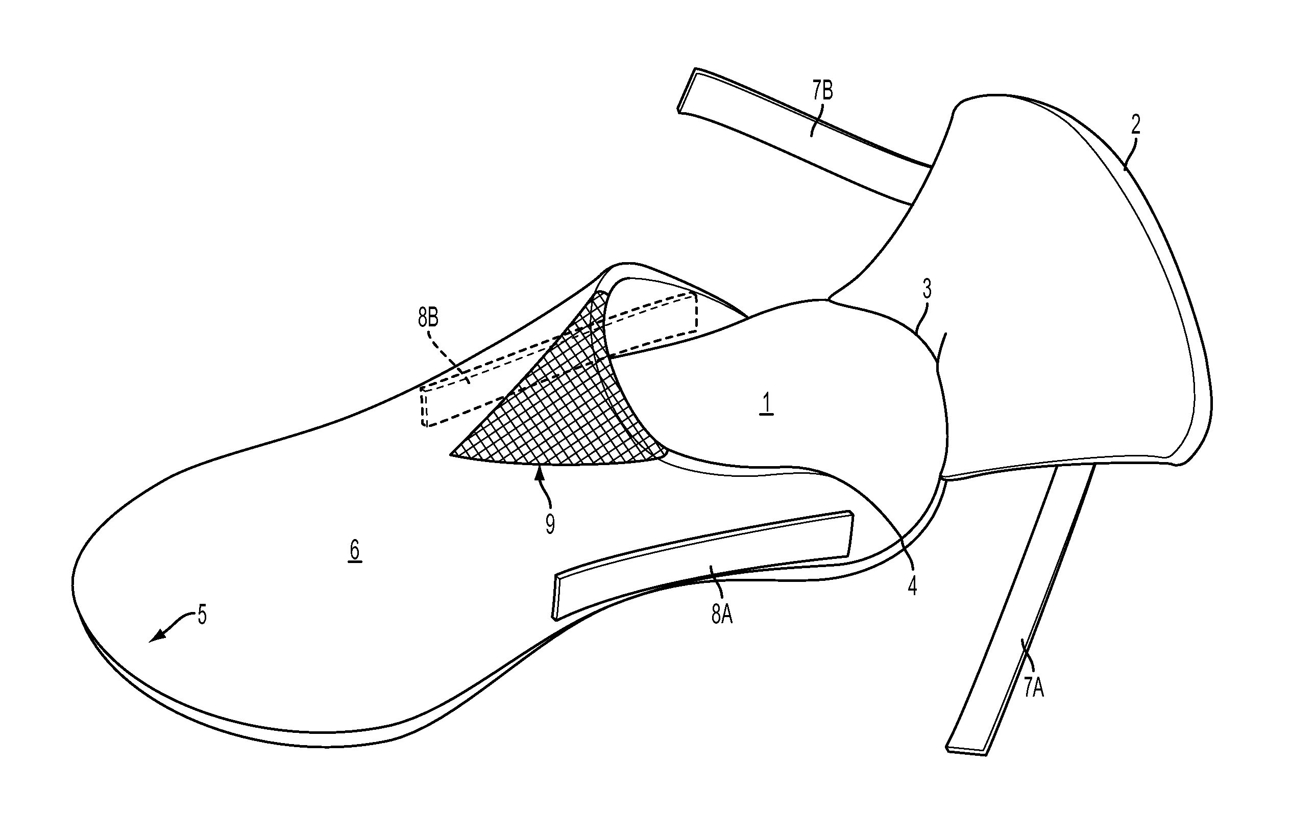
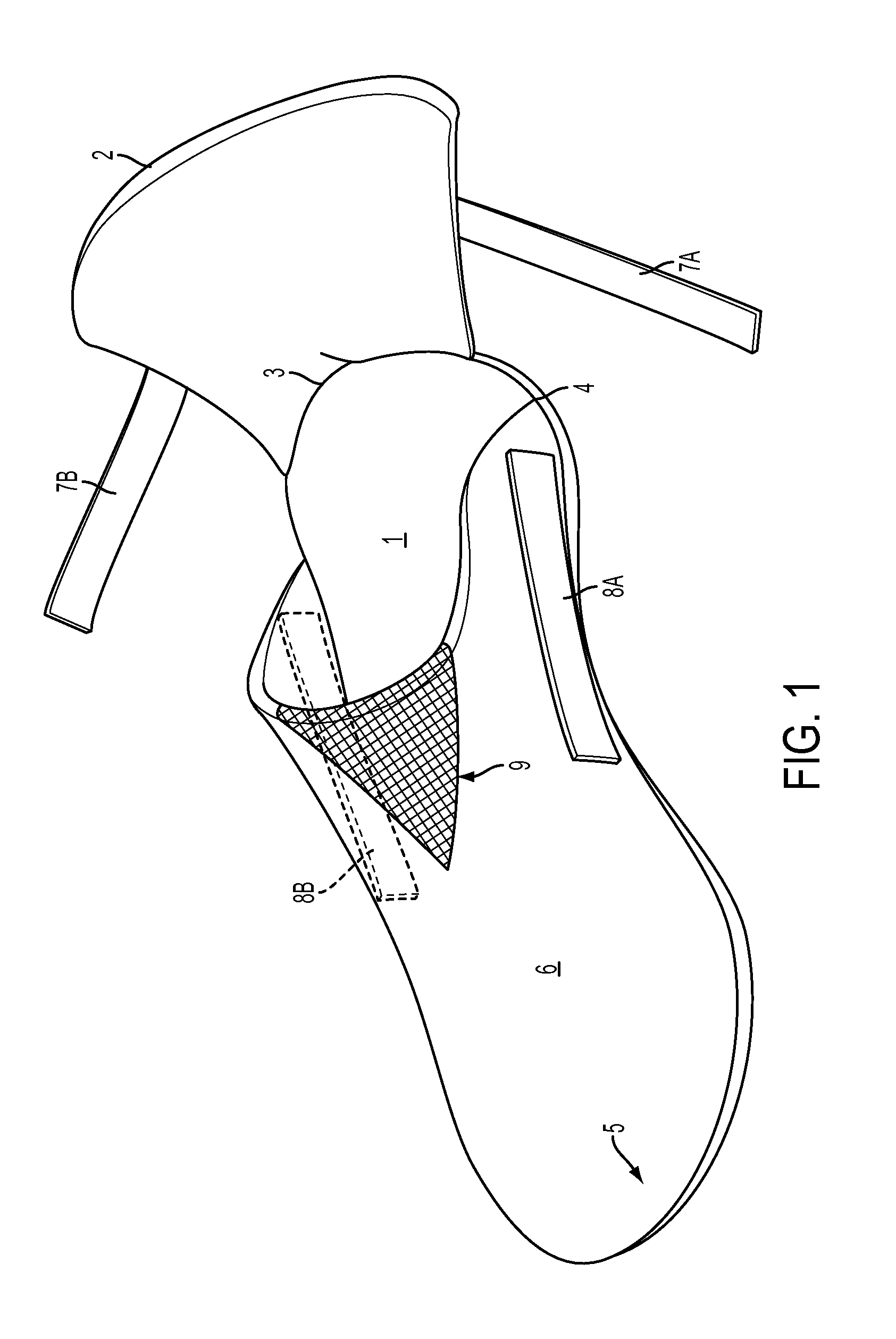
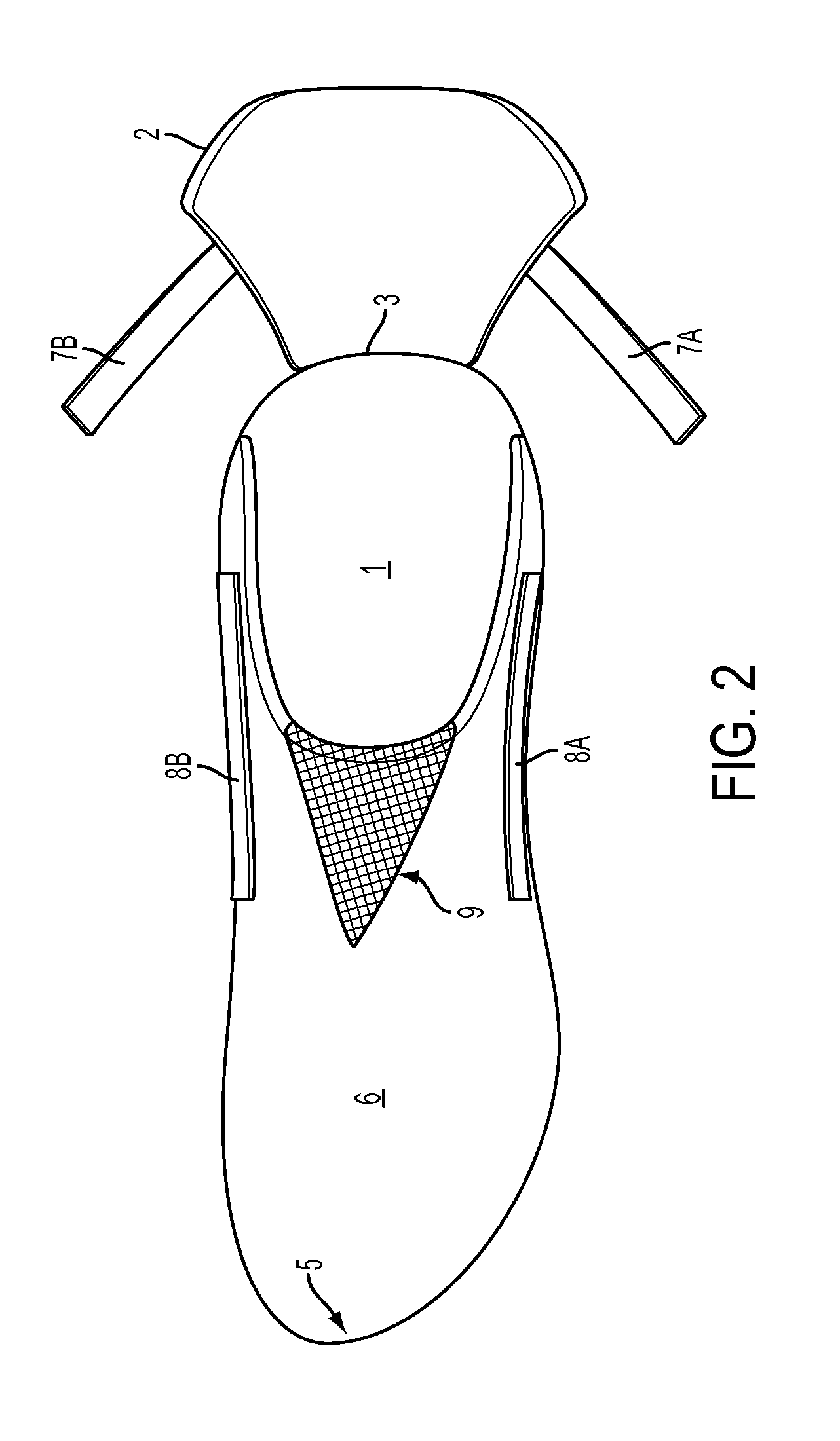
[0047]Turning to another embodiment, FIG. 6 shows spring biased wires 9A and 9B inserted and secured inside Velcro-like straps 7A and 7B respectively to stiffen and bend the straps outwardly and further away from the Velcro-like target patches 8A and 8B which they will eventually be moved to make contact with. The addition of the spring biased wires or equivalent provides additional assurance that the Velcro-like straps will not accidentally touch the wrong location spot on the nearby Velcro-like target patches. This embodiment prevents closure at an undesired location spot. While the running shoes of the first embodiment as described above in FIGS. 1 to 5 does not require the addition of these spring biased wires or similar additional support in the Velcro-like straps, the addition thereof adds further confidence and insurance against premature, accidental sticking before full closure. In short, this embodiment provides the athlete with assurance that the Velcro-like straps will no...

third embodiment

[0052]the running shoe of the disclosure is shown in FIG. 9. Here the strap and spring embodiments shown in FIGS. 1 to 6 are replaced with a modified heel or heel counter portion as will now be described. Referring to FIG. 9, the heel or heel counter portion 21 is a retractable flap, which for illustrative purposes only, is 6 to 8 inches wide horizontally (depending on the shoe size), and 2.5 to 3.5 inches in height, vertically. The heel counter portion 21 includes flaps 22B and 23B extending outwardly from the sides of the heel counter portion 21. As detailed below, the flaps 22B and 23B have a fastening material disposed on the inner surfaces thereof and can be secured to corresponding fastening material disposed on an outer surface of the rear portion of the shoe so as to secure the heel counter portion 21 in the closed position. In the given embodiment, the heel center portion 21 and the flaps 22B and 23B are formed as one integral member. As shown in FIG. 9, the heel counter po...

fourth embodiment

[0054]the running shoe of the disclosure is shown in FIG. 10 where a one strap design is employed instead of the two strap design shown in FIGS. 1 to 6. The single flap allows the opening and secure closure of the middle portion of the heel counter portion in a faster and more efficient way than requiring two straps on each shoe as disclosed in FIGS. 1 to 6. In this embodiment, the heel is cut from the center top to the midsole area at its bottom approximately 1 inch on both sides, resulting in a 2 inch opening, The single flap (or strap) portion 24A of the heel counter portion is coated or formed with a hook / hole or equivalent material such as Velcro or a Velcro-like material, or any other suitable fastening material, and is set in the open position. The surface of the shoe is also coated or formed with a similar hook / hole or equivalent material such as Velcro or a Velcro-like material. For illustrative purposes only, the runner's left foot shoe is shown and the flap 24A is to be c...


PUM


Abstract

A running shoe design focused on the heel section of running shoes used in, for example, T2 transition phase of the sport of triathlon. A heel counter portion of the shoe is a retractable flap. The flap retracts to an open position at a 45 to 90 degree angle awaiting the unhindered insertion of the runner's foot without any need for the runner to bend or sit. Immediately after the foot is inserted, the flap is closed with a pressing forward action by the athlete's other foot. The flap and the sides of the shoe are coated with adhesive, velcro-like materials. A variation of the foregoing uses a heel counter cut from the center top to the midsole area at the bottom, resulting in an acceptable size opening for uninhibited foot insertion when the flap (or strap) portion of the heel counter is set in the open position.

Description

[0001]This is a continuation in part of application Ser. No. 14 / 174,969 filed Feb. 7, 2014, the content of which is incorporated by reference herein in its entirety.BACKGROUND OF THE INVENTION[0002]In conventional triathlon competition, there are three race segments—swim / bike / run, over which the total race time is measured. There are also two transition phases between the three race segments. There is a first transition stage “T1” between the initial leg of a triathlon, namely, the swim and the second event segment, the bike. The bike segment is followed by a second transition stage, called “T2.” This is the zone between the bike and the run segments. Thus, the total amount of time the athlete spends in each of the three racing segments, plus the two transition stages, all add up to determine the athlete's race time.[0003]In other words, seconds spent in the transition areas are every bit as precious to the competitor as the time required to complete the swim, bike and run segments ...

Claims


Application Information

Patent Timeline
Patent Type & Authority Patents(United States)
IPC IPC(8): A43B21/00A43B5/06A43B21/36
CPCA43B5/06A43B21/36A43B1/0081A43B23/0295A43C11/002A43C11/1493A43C15/005
Inventor ARDELL, DONALD BLUPO, RAPHAEL V
Owner ARDELL DONALD B
Why Eureka
Try Eureka