Fuel system and method

a fuel system and fuel technology, applied in the field of fuel systems, can solve problems such as potential fire/explosion hazards, and achieve the effect of preventing icing of components

Active Publication Date: 2015-09-29
AIRBUS OPERATIONS LTD
View PDF4 Cites 33 Cited by
  • Summary
  • Abstract
  • Description
  • Claims
  • Application Information

AI Technical Summary

Benefits of technology

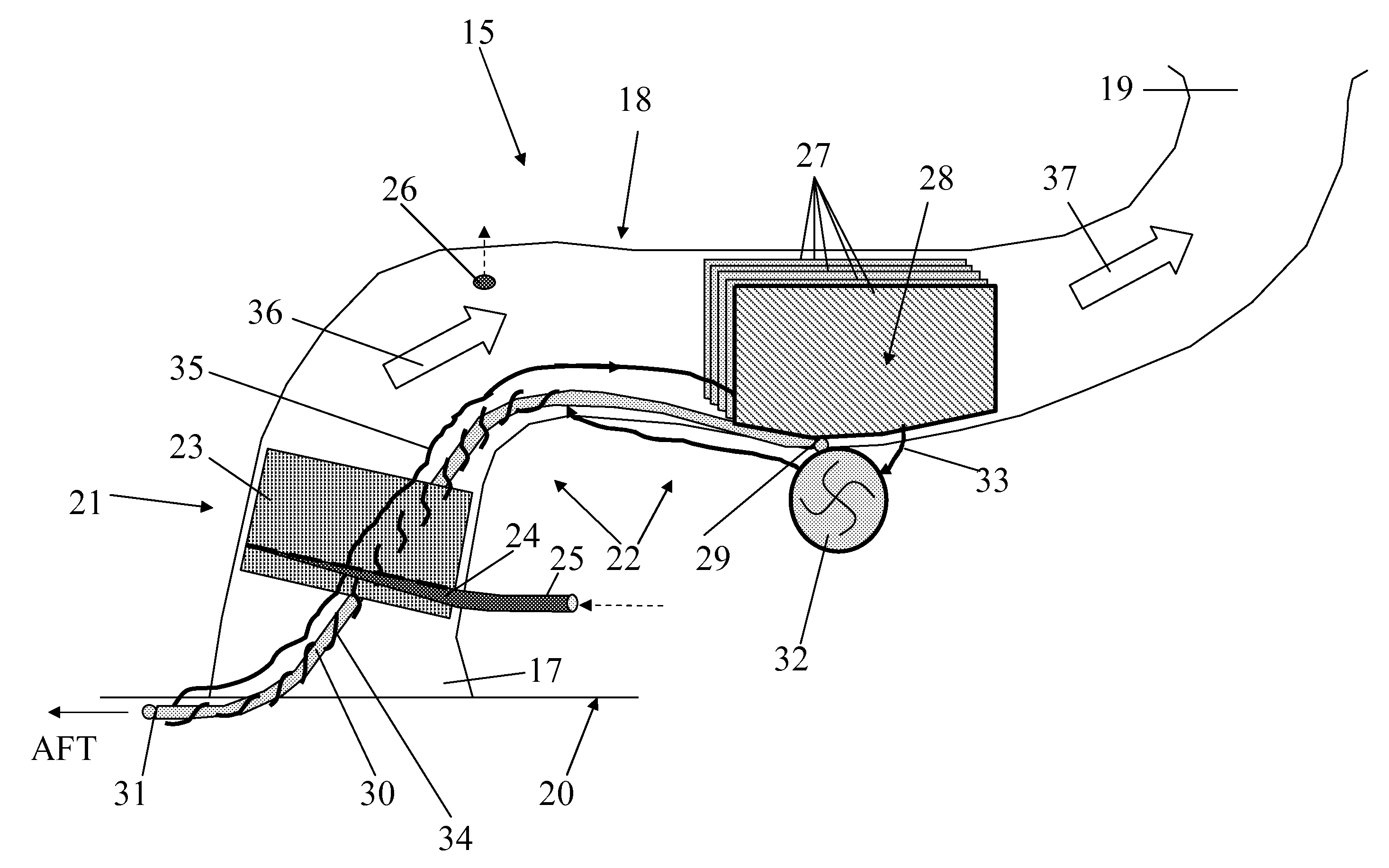
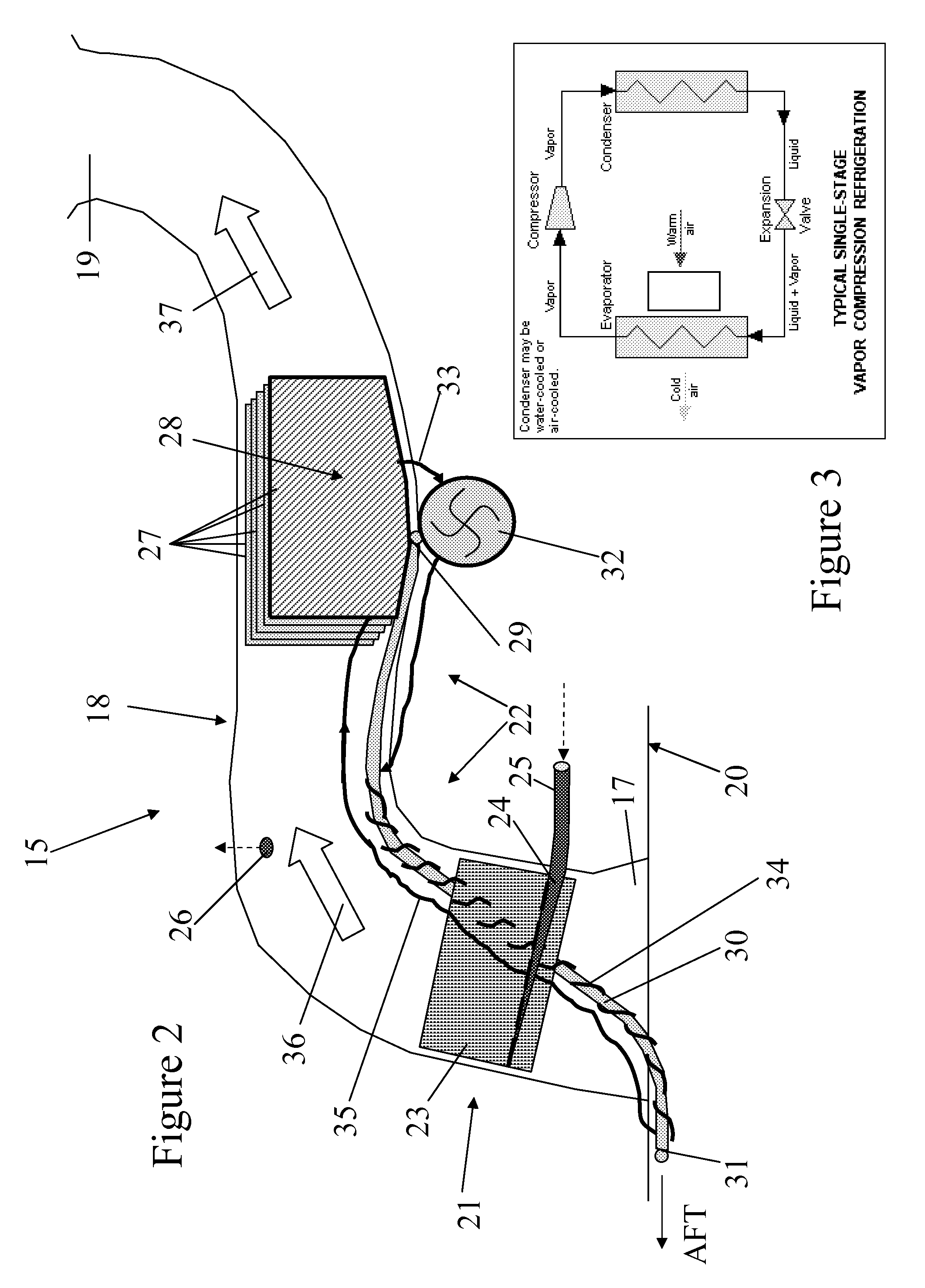
[0009]This invention is advantageous in that by providing the catalyst in the duct, the catalyst can be used to reduce the oxygen content of ambient air flowing through the duct towards the ullage, thereby inerting the ullage. Since the ingress ullage air is Mated at source, i.e. at the duct, there is no requirement for inerting distribution pipework, saving wing installation costs and weight.
[0010]For the catalytic reaction, a supply of fuel vapour may be fed to the catalyst. Preferably, the fuel vapour is extracted from the ullage. The fuel system therefore preferably includes a vapour feed line for delivering a supply of fuel vapour from the ullage into contact with the catalyst. This has the additional advantage of reducing the fuel vapour content of the ullage as well as its oxygen content. Of course, the catalyst could be supplied with fuel from another source, if desired.
[0014]The system may further comprise a dehumidifying device disposed in the duct between the catalyst and the interior of the vent tank. The dehumidifying device may be beneficial since a product of fuel combustion by the catalyst is water, which is an undesirable contaminant in fuel systems. By providing the dehumidifying device between the catalyst and the interior of the vent tank, water from the ambient air and / or generated by the catalytic reaction may be substantially removed from the air flowing towards the interior of the vent tank through the duct. This reduces the need for water drainage maintenance of the fuel tanks.
[0018]The cold plate may have a plurality of ribs on its surface. As water (either from the ingress ambient air or generated by the catalytic reaction) condenses out of the air flow on the surface of the cold plate through nucleation and growth it beads in grooves between the ribs. The cold plate may be arranged substantially vertically with the ribs inclined with respect to the direction of the in-flowing air. The combined effect of gravity and the air flow encourages the water beads to flow towards the bottom of the plate. To increase the efficiency of the refrigerative dehumidifying device, the cold plate may be one of an array of similar cold plates. These may be arranged side by side to allow the air flow to pass between adjacent plates.
[0019]Water from the refrigerative dehumidifying device may be collected in a sump. In a preferred embodiment, the sump is disposed beneath an array of vertically arranged cold plates. The location and shape of the sump can be tailored according to the refrigerating element(s) used. The sump may need to be drained and this may be done periodically, e.g. during maintenance activities, but is preferably done continuously whilst the device is operating. For example, a discharge tube may be used to pass condensate from the refrigerating element to the ambient atmosphere. The discharge tube may be connected at one end to the sump. Where the fuel system is used on a vehicle, e.g. an aircraft, the other end of the discharge tube may be exposed to airflow over the vehicle. Motion of the vehicle may be used to generate suction within the discharge tube drawing the water out into the atmosphere. This is preferable as no active pumping is required, which reduces power consumption and parts. However, a pump may be used if desired.
[0021]Waste heat from the catalytic reaction may be used to prevent icing of components of the dehumidifying device, e.g. the discharge tube and / or the refrigerating elements.

Problems solved by technology

The ullage can contain reactive components, such as oxygen and / or fuel vapours, which can be a potential fire / explosion hazard.

Method used


Image

  • Fuel system and method
  • Fuel system and method
  • Fuel system and method

Examples


Embodiment Construction

)

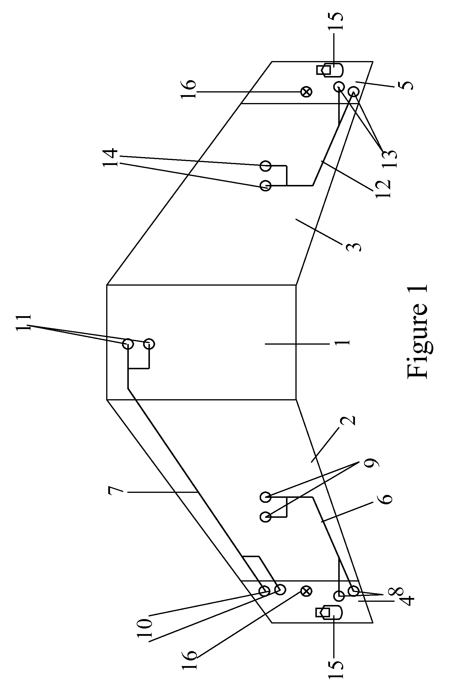
[0032]FIG. 1 shows a general ventilation system architecture for a three-tank configuration of an aircraft fuel system. The fuel system includes a centre tank 1, a left wing tank 2 and a right wing tank 3. The ventilation system includes a left vent tank 4 and a right vent tank 5. The left vent tank 4 ventilates the centre tank 1 and the left wing tank 2 by means of ventilation pipes 6, 7 which open into ventilation inlets 8, 9, 10, 11. The right vent tank 5 ventilates the right wing tank 3 by means of ventilation pipe 12 which opens into ventilation inlets 13 and 14.

[0033]Each vent tank 4, 5 includes a NACA duct assembly 15 including a NACA vent, or NACA scoop, which opens to the atmosphere on the lower aerodynamic surface of the aircraft wing. The vent tanks 4, 5 further include an over pressure protector 16.

[0034]One of the NACA duct assemblies 15 is shown schematically in FIG. 2. The NACA duct assembly 15 includes a vent (or inlet) 17, a duct 18, and a “bellmouth” outlet 19. Th...


PUM

PropertyMeasurementUnit
temperatureaaaaaaaaaa
catalytic temperatureaaaaaaaaaa
temperatureaaaaaaaaaa

Abstract

A fuel system includes a fuel tank, a vent tank fluidically connected to the fuel tank ullage, the vent tank having a duct open to the ambient atmosphere and the interior of the vent tank, and a catalyst disposed in the duct, wherein the catalyst is adapted to deplete one or more reactive components of gas flowing through the duct by catalytic reaction. Also, a method for depleting one or more reactive components of gas in the fuel system, includes depleting one or more reactive components of gas flowing through the duct using the catalyst.

Description

RELATED APPLICATIONS[0001]The present application is based on, and claims priority from, Great Britain Application Number 1006213.1, filed Apr. 14, 2010, the disclosure of which is hereby incorporated by reference herein in its entirety.FIELD OF THE INVENTION[0002]The present invention relates to a fuel system and to a method for depleting one or more reactive components of gas in a fuel system.BACKGROUND OF THE INVENTION[0003]Fuel tanks for storing liquid fuel are used, for example, for transporting or storing fuel and on vehicles for their propulsion systems. The volume of gas above the liquid fuel within the fuel tank is known as the ullage. The ullage can contain reactive components, such as oxygen and / or fuel vapours, which can be a potential fire / explosion hazard. The term “inerting” refers to the process of depleting one or more of these reactive components to reduce this potential hazard.[0004]Various inerting systems are known in the art. For example, the potentially explos...

Claims


Application Information

Patent Timeline
Patent Type & Authority Patents(United States)
IPC IPC(8): B01D53/75B01D53/86B01D53/26
CPCB01D53/265B01D53/75B01D53/8668B01D53/8671B01D2255/10B01D2257/104B01D2257/7022B01D2258/02B01D2259/4575
Inventor TICHBORNE, FRANKLINLAM, JOSEPH K - WPARMENTER, DAVIDMASTERS, SIMON
Owner AIRBUS OPERATIONS LTD
Why Eureka
Try Eureka