Adaptive gunner protection kit

a protection kit and gunner technology, applied in the field of gunner protection systems, can solve the problems of large diameter of the barrel of the weapon that cannot fit within the narrow vertical slot suitable for machine guns, the overall geometry of armored envelopes sized for machine guns and grenade launchers is often too small to fit the often substantially bulkier dimensions of missiles or rocket launchers and other large weapon systems, and achieves the effect of increasing the size of the armored envelop

Active Publication Date: 2015-09-29
BAE SYSTEMS LAND & ARMAMENTS LP
View PDF31 Cites 7 Cited by
  • Summary
  • Abstract
  • Description
  • Claims
  • Application Information

AI Technical Summary

Benefits of technology

[0008]The present invention is directed to an adapted gunner protection system that comprises a plurality of armored panels that can be arranged around the roof hatch of a vehicle to provide an armored envelope for protecting a gunner operating a roof mounted weapon or equipment system. The panels can be arranged to define at least one opening through which the weapon or equipment system can be operated. Each armored panel is rotatably mounted to the vehicle roof such that each panel can be individually raised to a generally vertical orientation to define a portion of the overall armored envelope or lowered to a position against the vehicle roof to increase the size of the armored envelope or create a second opening in the armored envelope. The individual positioning of the armored panels allows the size and shape of the armored envelope and opening to be customized for the particular weapon or equipment system mounted to the vehicle at that time. The armored envelope can be increased in size or provide additional openings for addressing back blast from certain weapon systems. Similarly, all of the panels can be lowered against the roof of the vehicle to collapse the armor panel without disengaging the panels from the vehicle allowing for efficient transport of the vehicle without the additional difficulty of attaching the armor system in theatre.
[0009]In one aspect, at least one of the armored panels can be upright when rotated into the vehicle orientation. In another aspect, at least one of the armored panels can be angled radially inward toward the center of the hatch when raised to the vertical orientation. In this configuration, two adjoining panels that are inwardly angled can be engaged together along a common edge, wherein the inward angle of the armored panels cooperates to maintain the panels in the generally vertical orientation without requiring an additional support structure to prevent the armored panels from collapsing inward from impacts to the exterior of the armored envelope. The inwardly angled armored panels also provide protection from ballistic threats directed from angles above the horizontal. In yet another, aspect, at least one of the panels can be angled outward to provide clearance for certain weapons and equipment system. Similarly, the outward angle of the panels can provide an angled surface for directing the back blast of certain weapon systems, such missiles, rockets or recoilless rifles, upwards away from the vehicle rather than downward toward the vehicle roof or back toward the weapon system or gunner. The panels are rotated radially outward to lower the panels into the generally horizontal position to collapse all or a portion of the armored envelope.
[0012]In an embodiment of the present invention, the fore panels, the side panels or back panel can each comprise a transparent armored window. The armored windows allow for increased visibility through the armored panels without requiring an additional slot or opening for providing a sight line through the armored envelope. In one aspect, the armored windows can be positioned in the armored panels to correspond to the sight lines of the gunner when operating the weapon or equipment system.
[0013]In an embodiment of the present invention, the gunner protection system can comprise a gun shield mountable to the weapon system. The gun shield further comprises an armored panel defining a slot for receiving the barrel or a portion of the action of a weapon system. The gun shield further comprises a weapon mount for attaching the panel to the weapon system. The gun shield is positioned on the weapon system such that the edges of the armored panel overlap with the edges of the opening defined by the fore panels to eliminate a direct path through the armored envelope between the gun shield and the fore panels. In one aspect, the overlap between the gun shield and fore panels can be sized such that the weapon system can be rotated and aimed during operation of the weapon system without creating gaps between the gun shield and fore panels.

Problems solved by technology

With large bore weapons such as MK19 grenade launcher or M120 / M121 mortars, the larger diameter of the barrel of those weapons may not fit within the narrow vertical slot suitable for machine guns.
Thus the vertical slot used for machines guns cannot accommodate the high angles necessary to operate grenade launchers or mortars.
In addition, the overall geometry of armored envelopes sized for machine guns and grenade launcher is often too small to fit the often substantially bulkier dimensions of missile or rocket launchers and other large weapon systems.
The limited confines of the armored envelope can also present safety hazards for the gunner when operating missile launchers or other systems that produce significant back blast.
A similar drawback is that targeting systems used for painting targets for airstrikes or artillery fire are also often large and bulky making them incompatible with the often smaller envelope geometry created by GPKs for machine guns.
The specific requirements of individual weapons and equipment systems typically requires that the entire GPKs be replaced when a different weapon or targeting system is to be mounted, thereby substantially increasing the logistical challenges of providing adequate protection for the gunner.
A similar challenge with GPKs is that the armored envelope formed by the GPK can substantially increase the overall height of the vehicle.
As the GPKs are often fitted to the vehicle before the armored vehicles are transported into the theater by ship or plane, the added height can make efficiently transporting the vehicles to the theater within the limited confines of a ship or plane difficult.
However, the inherent drawback of this approach is that the assembly process must be done in theater where maintenance and other equipment necessary for assembly may be more limited.
In addition, the assembly process creates substantial downtime where the vehicle is otherwise ready for use, but is awaiting installation of the GPK.

Method used


Image

  • Adaptive gunner protection kit
  • Adaptive gunner protection kit
  • Adaptive gunner protection kit

Examples


Embodiment Construction

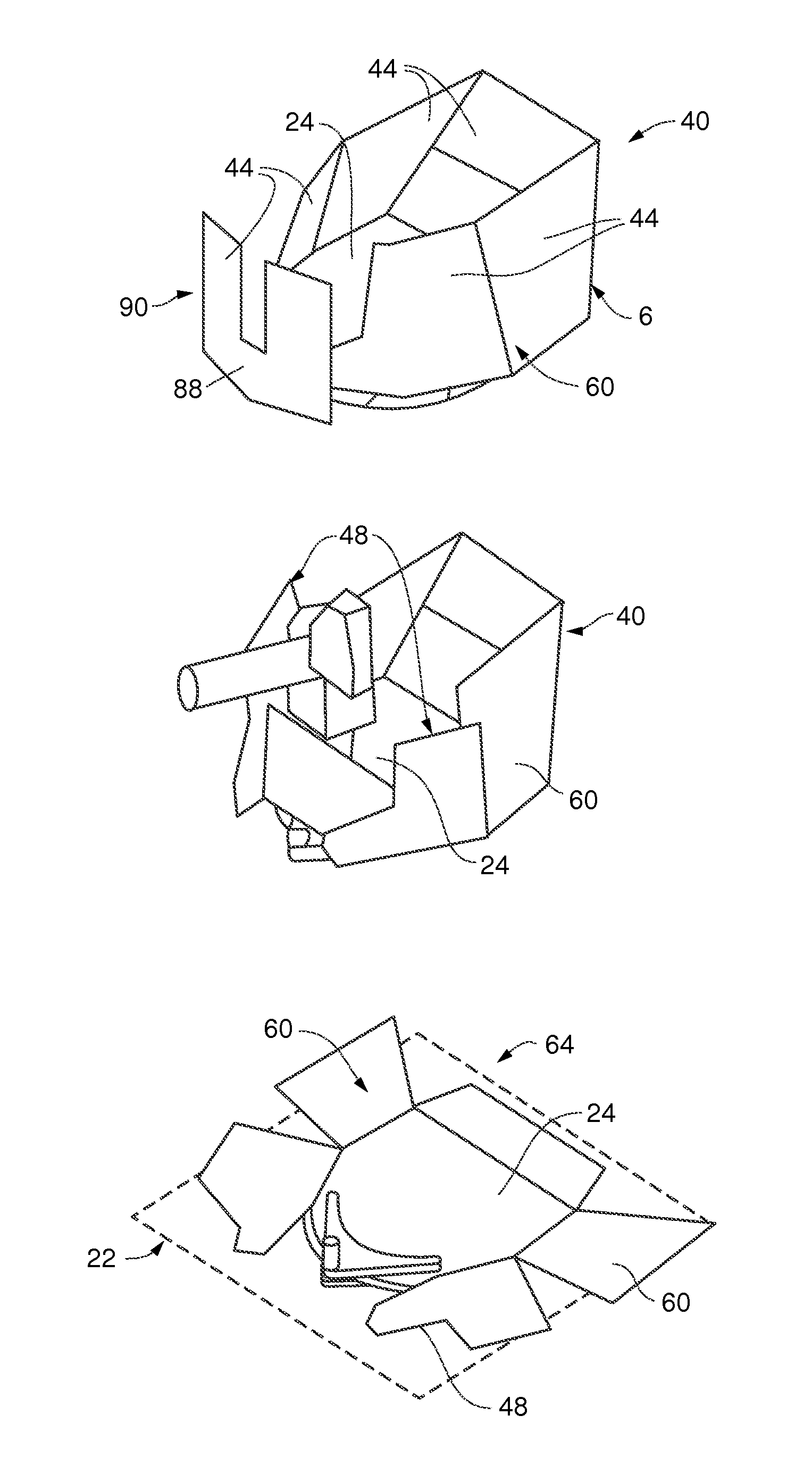
[0039]As depicted in FIGS. 3-7, a vehicle 20, for use with the present invention, comprising a roof 22 with a hatch 24 defining a hatch opening 26 through the roof 22. The hatch 24 further comprises a door 28 rotatable between a closed position in which the hatch door 28 is positioned within the hatch opening 26 to seal the hatch opening 26 and an open position in which the door 28 is rotated out of the hatch opening 26 to allow passage through the opening 26. As depicted in FIG. 5-7, the door 28 comprises a multi-fold hatch door such that the door 28 can be folded in half or thirds after the door 28 is rotated into the open position to reduce the footprint of the door 28 after opening. Alternatively, the door 28 can comprise a fixed panel door as depicted in FIG. 4. In one aspect, the hatch 24 can further comprise a hatch ring 30 encircling the hatch opening 26 and to which the hatch door 28 is rotatable mounted. In one aspect, the hatch ring 30 can comprise a weapon / equipment moun...


PUM


Abstract

A gunner protection system for positioning armored panels around a hatch opening and a mounted weapon or equipment system. The armored panels are arranged to create an armored envelope surrounding the vehicle hatch and defining an opening through which the weapon or equipment system can be operated. The armored panels can be individually raised to define a portion of the armored envelope or lowered to change the geometry of the armored envelope or opening according to the particular weapon or equipment system. Similarly, all of the armored panels can be lowered to collapse the armorer envelope to allow for efficient transport of the vehicle with the gunner protection system attached to the vehicle.

Description

RELATED APPLICATION[0001]The present application claims the benefit of U.S. Provisional Application No. 61 / 534,605 entitled “Adaptive Gunner Protection Kit”, filed Sep. 23, 2011, which is incorporated herein by reference in its entirety.FIELD OF THE INVENTION[0002]The present invention is directed to a gunner protection system for positioning armor panels on the roof of armored vehicles to create an armored envelope protecting gunners operating roof mounted weaponry or equipment. Specifically, the present invention is directed to an adaptive gunner protection system having armored panels that can be repositioned to change the geometry and size of the armored envelope to accommodate different weapons or equipment or to collapse the armored envelope for efficient transport of the vehicle.BACKGROUND OF THE INVENTION[0003]Lightly armored vehicles have recently seen increased use in urban combat situations in which a gunner operating a roof mounted weapon is often exposed to close quarte...

Claims


Application Information

Patent Timeline
Patent Type & Authority Patents(United States)
IPC IPC(8): F41H5/20F41H7/04F41H5/013F41H5/16
CPCF41H7/048F41H5/013F41H5/16F41H5/20F41H7/044
Inventor CHU, PETER C.KARIYA, BRIAN H.ARMSTRONG, JOHN HENRY
Owner BAE SYSTEMS LAND & ARMAMENTS LP
Why Eureka
Try Eureka