
Ultra-high vacuum metallic seal

a technology of metallic seals and ultra-high vacuum, which is applied in the field of seals, can solve the problems that elastomeric seals are generally not suitable for ultra-high vacuum (uhv) sealing applications and limit the sealing life, so as to reduce manufacturing costs, reduce sealing force, and minimize production steps

Active Publication Date: 2015-10-06
PARKER INTANGIBLES LLC
View PDF8 Cites 1 Cited by
  • Summary
  • Abstract
  • Description
  • Claims
  • Application Information

AI Technical Summary

Benefits of technology

[0017]The present invention includes a seal design that reduces manufacturing costs by minimizing production steps and also lowers the sealing force by incorporating a thin-wall, high height / width ratio annular column. The seal has two horizontal ribs which constrain the thin-wall column from unstable buckling to thereby reduce or eliminate the tendency of the sealing dams to become inclined to sealing flange surfaces.

Problems solved by technology

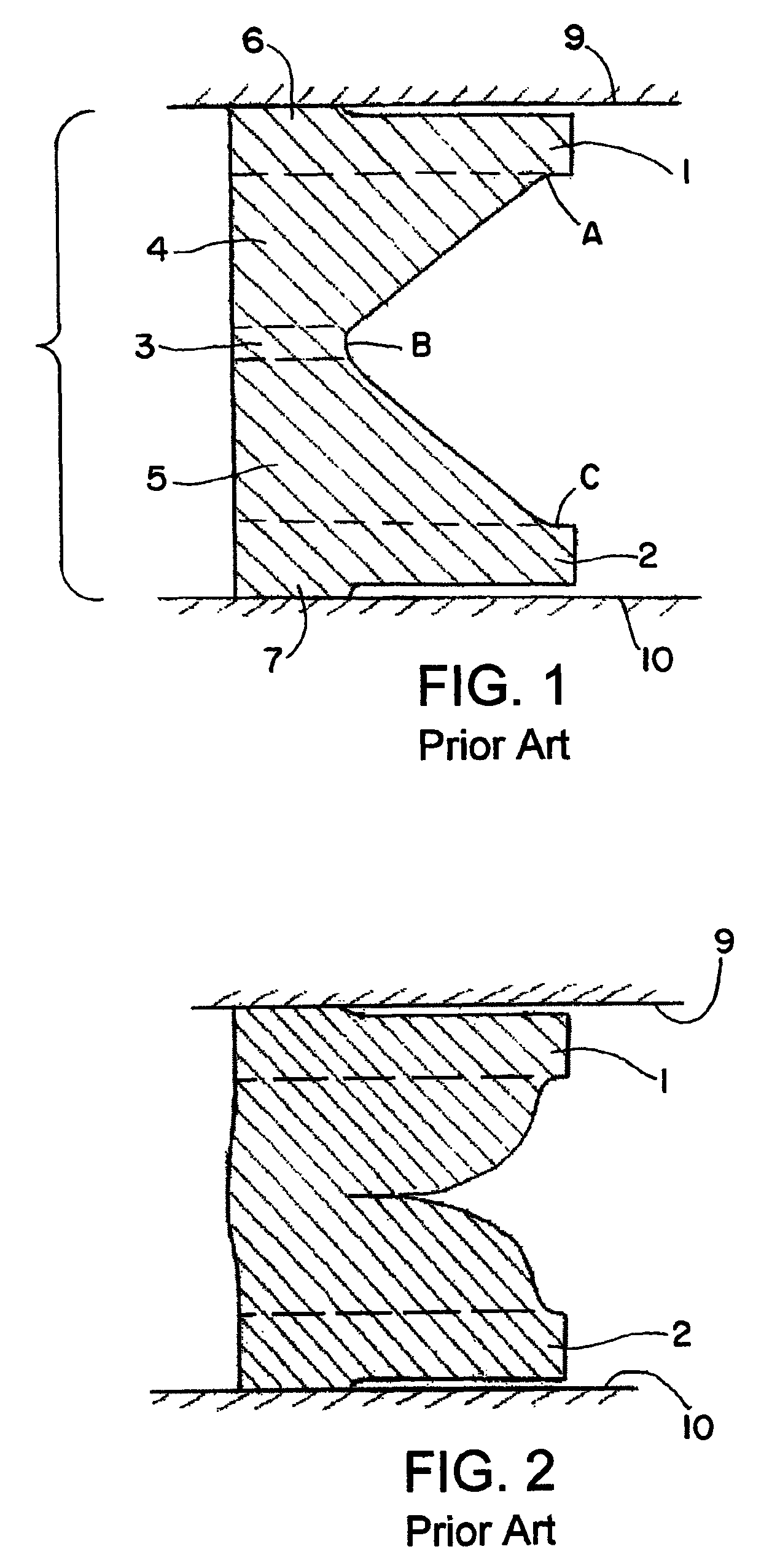
Elastomeric seals generally are not suitable for ultra high vacuum (UHV) sealing applications because of the inherent open structure of polymeric chains through which molecular gaseous species can diffuse.
Elastomeric seals are attacked by highly reactive radicals such as NF3 and O2 which severely damage the polymeric chain structure thereby limiting the seal life.

Method used


Image

  • Ultra-high vacuum metallic seal
  • Ultra-high vacuum metallic seal
  • Ultra-high vacuum metallic seal

Examples


Embodiment Construction

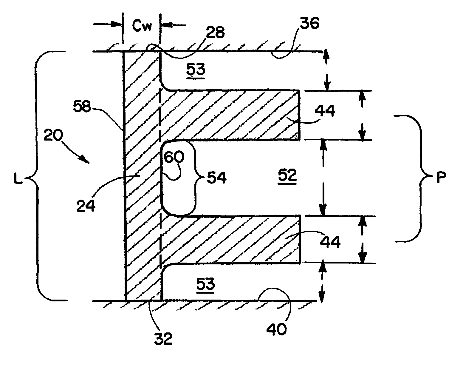
[0032]Turning now to FIGS. 4-7, and initially to FIG. 4, an exemplary metallic seal in accordance with the invention is generally indicated by reference numeral 20. The ring shape seal includes an annular column portion 24 surrounding a central axis A and having at opposite axial ends respective sealing dams 28 and 32 for engaging axially facing surfaces to be sealed, which as shown in FIGS. 5 and 6 are sealing flanges 36 and 40. Two ribs 44 extend radially from the column portion 24.

[0033]Turning to FIG. 5, the ribs 44 are axially spaced apart from each other and define therebetween an annular recess 52. The recess 52 in the illustrated embodiment is generally U-shape, and the ribs 44 generally extend perpendicular to the central axis A. The column portion extends axially beyond respective ribs 44 and define therewith respective recesses 53 that correspond in shape to one half of the annular recess 52.

[0034]As will be appreciated, the ribs 44 are axially spaced apart at a pitch P h...


PUM

PropertyMeasurementUnit
radial widthaaaaaaaaaa
diagonal brace angleaaaaaaaaaa
radial widthaaaaaaaaaa

Abstract

A metallic seal design that reduces manufacturing costs by minimizing production steps and also lowers the sealing force by incorporating a thin-wall, high height / width ratio annular column. The seal has two horizontal ribs which constrain the thin-wall column from unstable buckling to thereby reduce or eliminate the tendency of the sealing dams to become inclined to sealing flange surfaces.

Description

RELATED APPLICATIONS[0001]This application claims the benefit of U.S. Provisional Application No. 61 / 021,067 filed Jan. 15, 2008, which is hereby incorporated herein by reference.FIELD OF THE INVENTION[0002]The present invention generally relates to a seal for creating a seal between a pair of sealing surfaces and, more specifically, to a metallic seal.BACKGROUND OF THE INVENTION[0003]Elastomeric seals generally are not suitable for ultra high vacuum (UHV) sealing applications because of the inherent open structure of polymeric chains through which molecular gaseous species can diffuse. The lowest achievable He leak rate through elastomeric seals is typically 10−8 cc / sec. Using metallic seals, He leak rates in the range of 10−9-10−11 cc / sec can be easily obtained. Metallic seals, however, generally require high sealing force (Fs) also referred to as mechanical contact pressure Pmc where Pmc=Fs / As and As is the area of the sealing dam. If Pmc exceeds the yield strength of the sealing...

Claims


Application Information

Patent Timeline
Patent Type & Authority Patents(United States)
IPC IPC(8): F16J15/08
CPCF16J15/0887Y10T29/49995B23P13/04Y10T29/49996
Inventor DATTA, AMITAVAMA, HAI-PINGPAYNE, JEREMY
Owner PARKER INTANGIBLES LLC
Learn More