Roller Cone Drill Bit With Enhanced Debris Diverter Grooves

a technology of diverter grooves and drill bits, which is applied in earth-moving drilling, cutting machines, construction, etc., can solve the problems of shortening the life of associated roller cone drill bits, affecting the flow of fluids, and affecting the efficiency of drilling, so as to prolong the life of downhole drilling fluid seals, enhance the flow of fluids, and reduce the disadvantages of prior roller cone drill bits.

Inactive Publication Date: 2007-11-15
HALLIBURTON ENERGY SERVICES INC
View PDF4 Cites 4 Cited by
  • Summary
  • Abstract
  • Description
  • Claims
  • Application Information

AI Technical Summary

Benefits of technology

[0008]In accordance with teachings of the present disclosure, various disadvantages and problems associated with prior roller cone drill bits may be substantially reduced or eliminated. One aspect of the present disclosure may include extending the downhole drilling life of fluid seals which prevent small particles of shale, formation cuttings and other types of downhole debris from damaging bearings and associated bearing structures. For some applications, a roller cone drill bit may have at least one support arm with a debris diverter groove disposed in an interior surface of the support arm. The debris diverter groove may have variations in dimensions and / or configuration to enhance the flow of fluids containing shale, formation cuttings and other types of debris away from an associated fluid seal.

Problems solved by technology

Protection of bearings and related supporting structures which allow rotation of a cone assembly relative to an associated support arm and spindle may lengthen the life of an associated roller cone drill bit.
Once downhole debris is allowed to infiltrate between bearing surfaces of a cone assembly and associated spindle, failure of the associated drill bit will generally follow shortly.
Once the fluid seal fails, downhole debris may quickly contaminate bearing surfaces via the gap.
Tortuous fluid flow paths allow rotation of a cone assembly relative to an associated spindle but are often difficult for downhole debris to follow.
Such diverter plugs may block or direct fluids containing downhole debris away from an associated fluid seal.

Method used


Image

  • Roller Cone Drill Bit With Enhanced Debris Diverter Grooves
  • Roller Cone Drill Bit With Enhanced Debris Diverter Grooves
  • Roller Cone Drill Bit With Enhanced Debris Diverter Grooves

Examples


Embodiment Construction

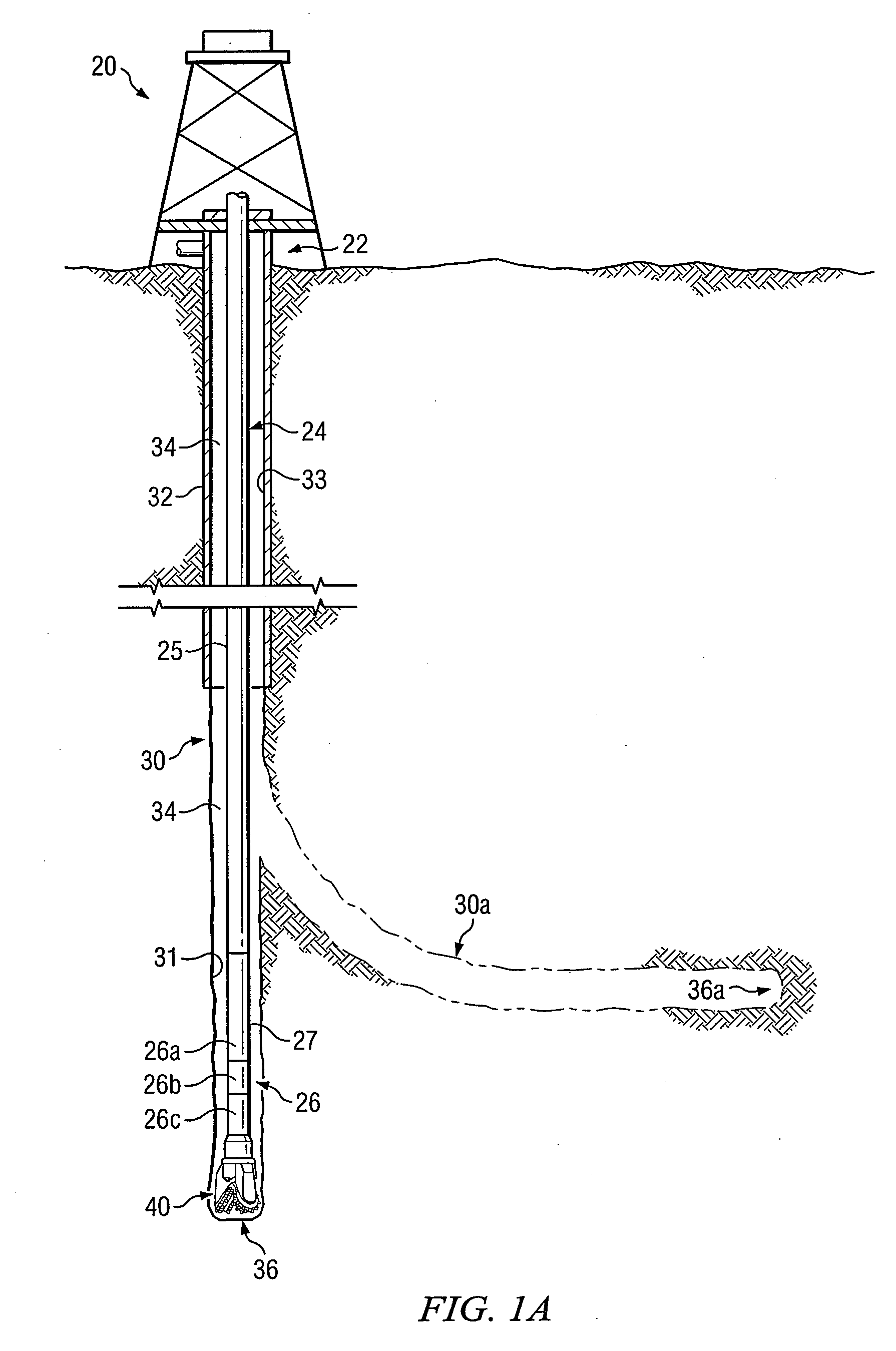
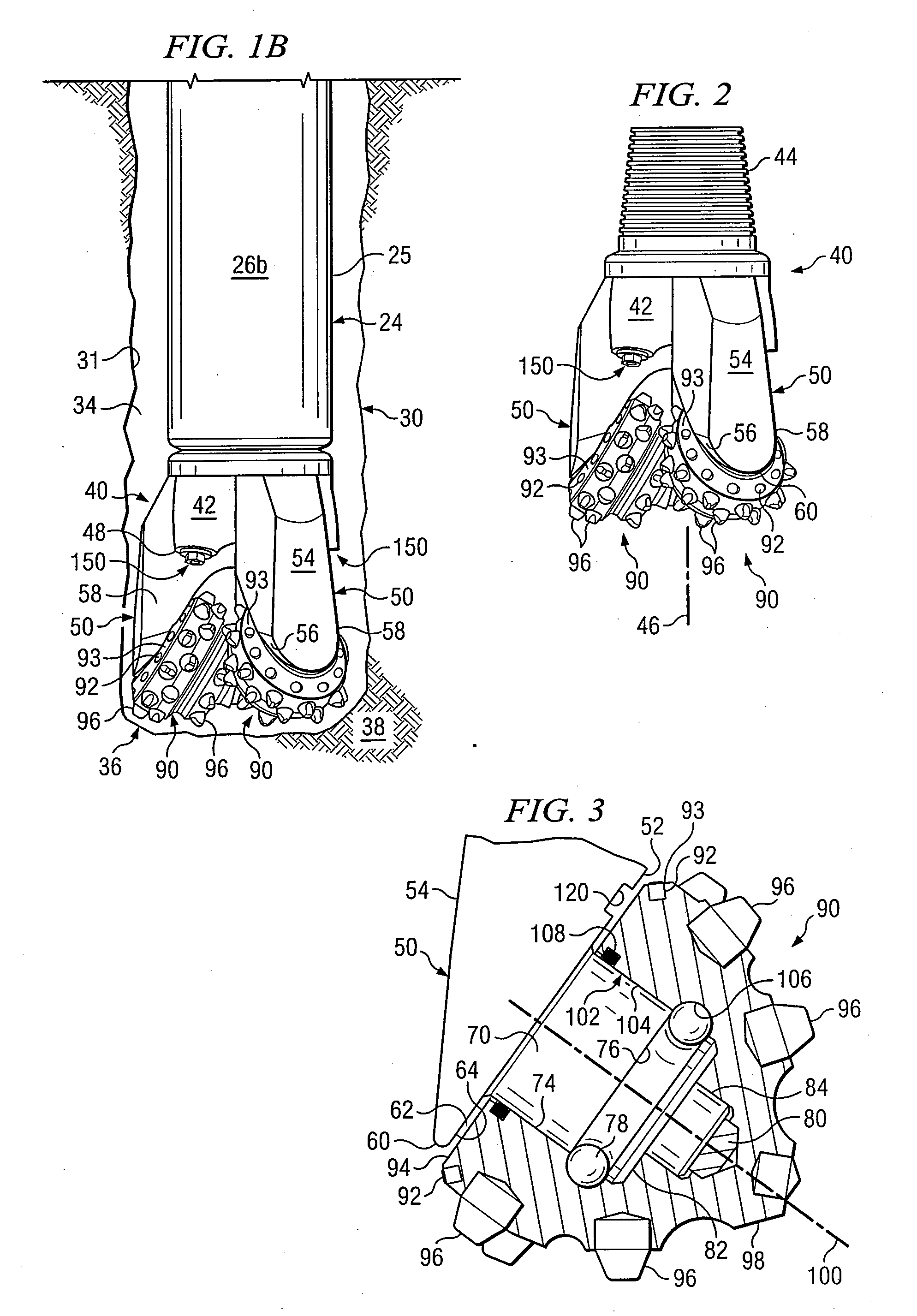
[0024]Preferred embodiments of the disclosure and its advantages are best understood by reference to FIGS. 1A-7D wherein like number refer to same and like parts.

[0025]The term “debris” may be used in this application to refer to any type of material such as, but not limited to, formation cuttings, shale, abrasive particles, or other downhole debris associated with forming a wellbore in a subterranean formation using a roller cone drill bit.

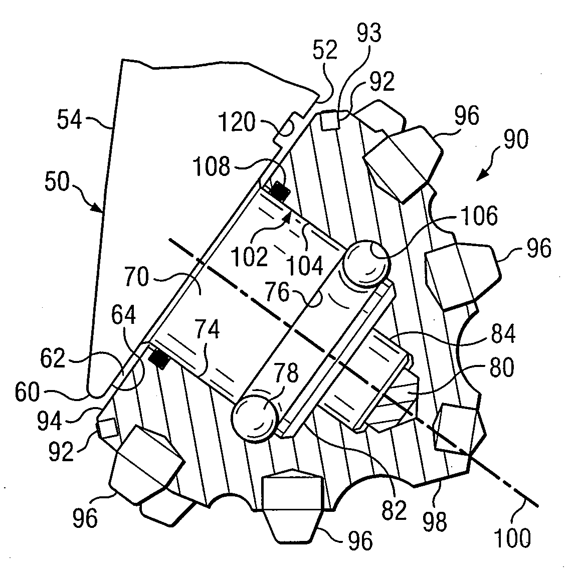
[0026]The term “diverter plug” may be used in this application to include any shale burn plug, shale diverter plug, debris diverter plug and debris diverter insert which may be installed in a support arm of a roller cone drill bit. Such diverter plugs may be used to block or redirect the flow of fluid containing downhole debris away from fluid seals in associated cone assemblies.

[0027]The term “cone assembly” may be used in this application to include various types and shapes of roller cone assemblies and cutter cone assemblies rotatably mounted ...


PUM


Abstract

A roller cone drill bit having a bit body with at least one support arm extending from the bit body. Each support arm may have an interior surface and exterior surface with an associated spindle extending from the interior surface. A respective cone assembly may be rotatably disposed on each spindle. A gap formed between interior portions of each cone assembly and exterior portions of the associated spindle with a fluid seal disposed in the gap to block fluid flow therethrough. Each cone assembly includes a generally circular back surface disposed adjacent to the interior surface of the associated support arm. A flow diverter groove formed in the interior surface of each support arm spaced from the associated spindle. Each diverter groove having a variable geometry to enhance the flow of fluid containing downhole debris away from the associated real assembly, and each diverter groove having a variable geometry.

Description

RELATED APPLICATIONS[0001]This application claims the benefit of provisional patent application entitled “Roller Cone Drill Bit With Enhanced Debris Diverter Grooves,” Application Ser. No. 60 / 775,648 filed Feb. 21, 2006.TECHNICAL FIELD[0002]The present disclosure is related to roller cone drill bits used to form wellbores in subterranean formations and more particularly to roller cone drill bits with debris diverter grooves.BACKGROUND OF THE DISCLOSURE[0003]A wide variety of roller cone and rotary cone drill bits have previously been used to form wellbores or boreholes in subterranean formations. Roller cone drill bits generally include at least one support arm and often three support arms. A respective cone assembly may be rotatably mounted on a spindle or journal extending inwardly from an interior surface each support arm. Small gaps are generally provided between adjacent portions of each support arm and associate cone assembly to allow rotation of the cone assembly relative to ...

Claims


Application Information

Patent Timeline
Patent Type & Authority Applications(United States)
IPC IPC(8): E21B10/08
CPCE21B10/25E21B10/18E21B10/22
Inventor WILLIAMS, MARK E.CRAWFORD, MICHAEL B.SAXMAN, WILLIAM C.BLACKMAN, MARK P.PRUITT, GERALD L.
Owner HALLIBURTON ENERGY SERVICES INC
Why Eureka
Try Eureka