Surface texture measurement device, controller for surface texture measurement device, and method for controlling the same

a measurement device and controller technology, applied in the direction of mechanical measurement arrangements, mechanical roughness/irregularity measurements, instruments, etc., can solve the problems of limited detection resolution, display errors, and inability to make detection resolution indefinitely larger, etc., to achieve the effect of measurement results

Active Publication Date: 2015-10-06
MITUTOYO CORP
View PDF9 Cites 3 Cited by
  • Summary
  • Abstract
  • Description
  • Claims
  • Application Information

AI Technical Summary

Benefits of technology

[0017]In the present invention as described above, when displaying measurement results on the display with the controller, display with a plurality of display ranges can be performed. In addition, gain error for the range amplifier performing display in each of the display ranges can be corrected (gain error correction) and the measurement results displayed by each display range can be made accurate. Specifically, one of the plurality of display ranges is used as the reference range to compute the gain error rate between the reference range and the other display ranges. The display resolution of each display range is then controlled based on the gain error rate. Accordingly, the gain can be controlled for each display range using the reference range as a reference. As a result of this gain error correction, display at the corrected display resolution using the reference range as the reference as well as resolution of a range error for the reference range become possible in all display ranges. The gain error correction also enables resolution of errors for each entire display range.

Problems solved by technology

In addition, a detection resolution is limited due to a performance of an A / D converter or due to a noise level of an amplifier, and thus the detection resolution cannot be made indefinitely larger.
In a surface texture measurement device, when switching between a plurality of display ranges to perform display, display errors may arise due to characteristics of a processing system for each display range or the like.
However, when there is an error in an amplifier for each range, there is a possibility that even when the measurement value is the same, a different display value will result for each display range.
Meanwhile, when switching between display ranges is performed automatically as in Japanese Patent Laid-open Publication No. 2000-310529, when a user controls each of the switches, the benefit of automation is undermined.
Offset errors are representative of errors between ranges; however, it has become clear that simply resolving offset errors is insufficient for resolving errors between ranges.
The offset error corresponds to parallel translation on the graph; however, actual errors between ranges also appear as an inclination in the graph.

Method used


Image

  • Surface texture measurement device, controller for surface texture measurement device, and method for controlling the same
  • Surface texture measurement device, controller for surface texture measurement device, and method for controlling the same
  • Surface texture measurement device, controller for surface texture measurement device, and method for controlling the same

Examples


Embodiment Construction

[0033]The particulars shown herein are by way of example and for purposes of illustrative discussion of the embodiments of the present invention only and are presented in the cause of providing what is believed to be the most useful and readily understood description of the principles and conceptual aspects of the present invention. In this regard, no attempt is made to show structural details of the present invention in more detail than is necessary for the fundamental understanding of the present invention, the description is taken with the drawings making apparent to those skilled in the art how the forms of the present invention may be embodied in practice.

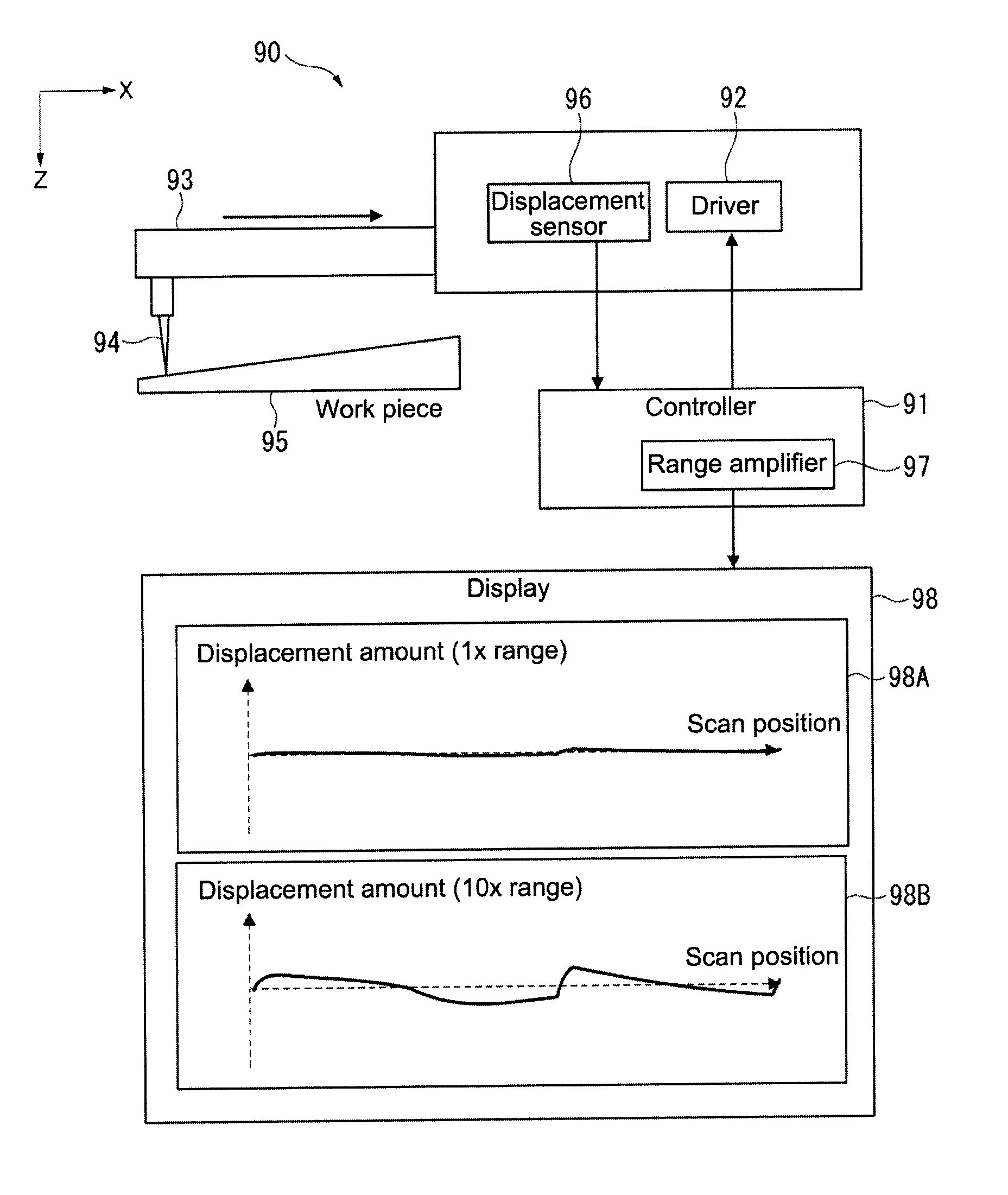
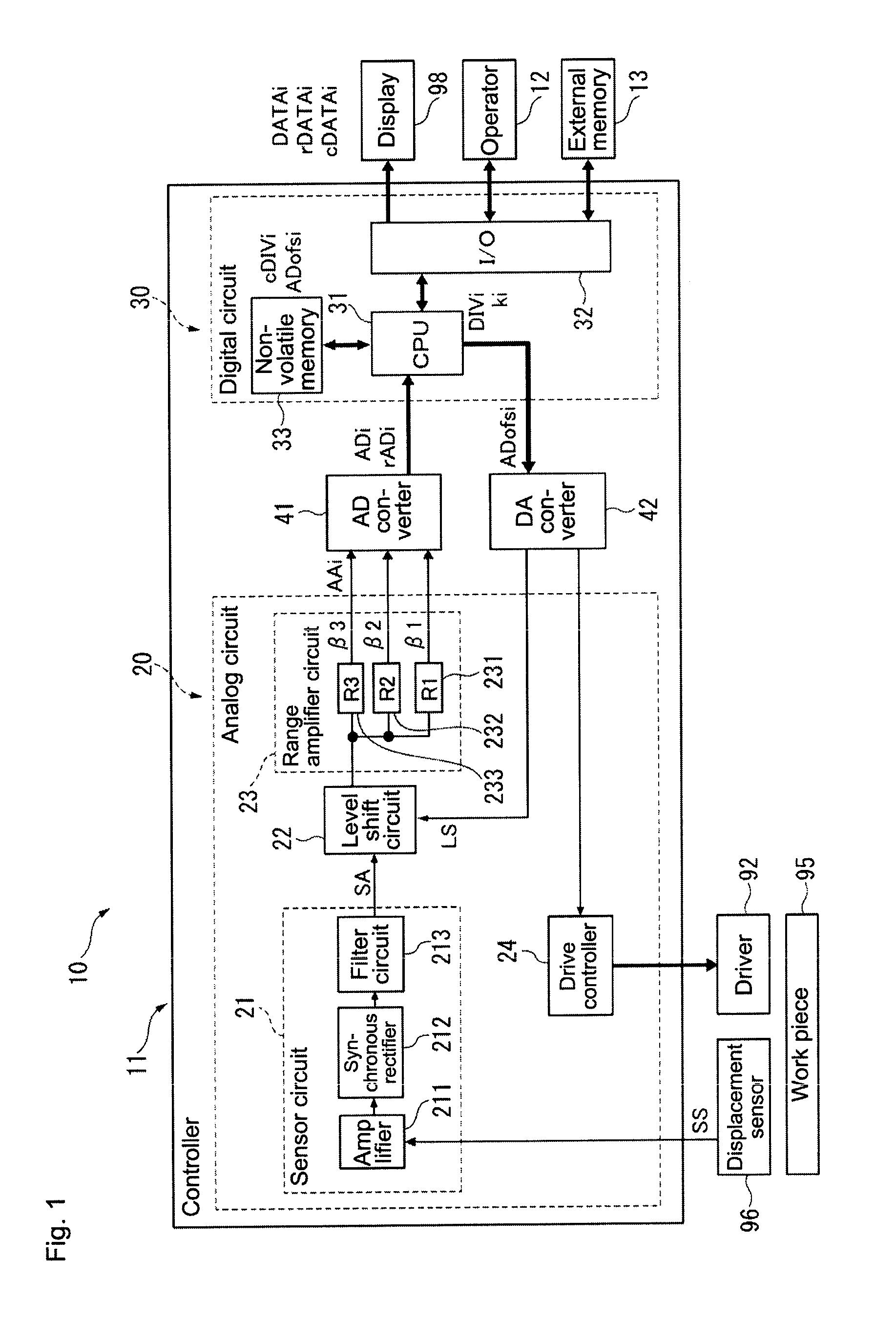
[0034]Hereafter, an embodiment of the present invention is described with reference to the drawings. In FIG. 1, a surface texture measurement device 10 according to the present embodiment is provided with a configuration similar to a conventional surface texture measurement device 90 (see FIG. 7) described above. Specifically,...


PUM

PropertyMeasurementUnit
voltageaaaaaaaaaa
surface textureaaaaaaaaaa
displacementaaaaaaaaaa

Abstract

A surface texture measurement device capable of resolving errors for each entire display range, a controller for the surface texture measurement device, and a method for controlling the surface texture measurement device that includes selecting any one of the display ranges as a reference range and defining a calibration measurement value for each display range; sequentially inputting the calibration measurement values in place of the measurement values to the range amplifier corresponding to the reference range to obtain a reference display value rDATAi; inputting the calibration measurement values to the range amplifiers corresponding to each display range, then obtaining an AD-converted value ADi and a display value DATAi; computing a gain error rate ki=rDATAi / DATAi, a display resolution DIVi=DATAi / ADi, and a corrected display resolution cDIVi=DIVi×ki; and displaying the corrected display value cDIVi=DIVi×ki.

Description

CROSS-REFERENCE TO RELATED APPLICATIONS[0001]The present application claims priority under 35 U.S.C. §119 of Japanese Application No. 2012-051976, filed on Mar. 8, 2012, the disclosure of which is expressly incorporated by reference herein in its entirety.BACKGROUND OF THE INVENTION[0002]1. Field of the Invention[0003]The present invention relates to a surface texture measurement device, a controller for the surface texture measurement device, and a method for controlling the surface texture measurement device. In particular, the present invention relates to a surface texture measurement device having a plurality of display ranges and to a method for controlling the surface texture measurement device.[0004]2. Description of Related Art[0005]Conventionally, a surface texture measurement device is known in which a surface of a work piece is scanned by a stylus to measure a surface texture thereof (surface roughness, undulations, shape in outline, and the like). In the surface texture ...

Claims


Application Information

Patent Timeline
Patent Type & Authority Patents(United States)
IPC IPC(8): G01B5/28G01N19/08G01B21/04G01B21/30
CPCG01B5/28G01B21/042G01B21/30
Inventor KANEMATSU, TOSHIHIROHONDA, HIROOMI
Owner MITUTOYO CORP
Why Eureka
Try Eureka