Optical signal quality monitoring method and apparatus using a software-based synchronized amplitude histogram

a software-based synchronized amplitude and histogram technology, applied in the direction of electrical equipment, electromagnetic transmission, transmission, etc., can solve the problems of difficult analysis of non-synchronized amplitude histogram and extracting a suitable parameter, constructive interference and destructive interference between continuous symbols, etc., to achieve cost-effective and accurate synchronization, monitor the quality of optical signals

Inactive Publication Date: 2015-10-06
KOREA ADVANCED INST OF SCI & TECH
View PDF4 Cites 0 Cited by
  • Summary
  • Abstract
  • Description
  • Claims
  • Application Information

AI Technical Summary

Benefits of technology

[0012]A further object of the present invention is to provide a clock signal for accurate synchronization by compensating a difference between a clock frequency of a Fourier-transformed data sample and an aliasing clock frequency.
[0030]In the optical signal quality monitoring method according to the present invention, it is possible to monitor a quality of an optical signal over a wide range by asynchronously sampling a detected optical signal and then generating a synchronized amplitude histogram. Moreover, it is possible to significantly enhance the monitoring accuracy of an optical signal quality.

Problems solved by technology

This poses a problem in that it is difficult to analyze the non-synchronized amplitude histogram and to extract a suitable parameter indicating a signal quality.
If chromatic dispersions are accumulated in an optical signal, constructive interference and destructive interference occur between continuous symbols.
This makes it difficult to analyze the non-synchronized amplitude histogram.
For that reason, this method is costly and is not widely used in the art.

Method used


Image

  • Optical signal quality monitoring method and apparatus using a software-based synchronized amplitude histogram
  • Optical signal quality monitoring method and apparatus using a software-based synchronized amplitude histogram
  • Optical signal quality monitoring method and apparatus using a software-based synchronized amplitude histogram

Examples


Embodiment Construction

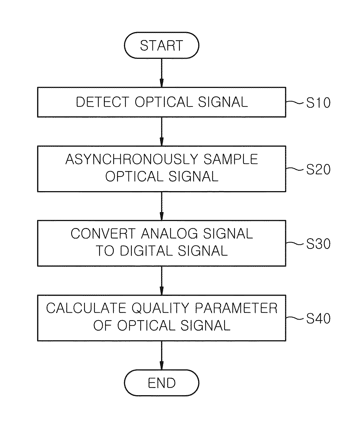
[0041]Certain preferred embodiments of an optical signal quality monitoring apparatus and method using a software-based synchronized amplitude histogram according to the present invention will now be described in detail with reference to the accompanying drawings.

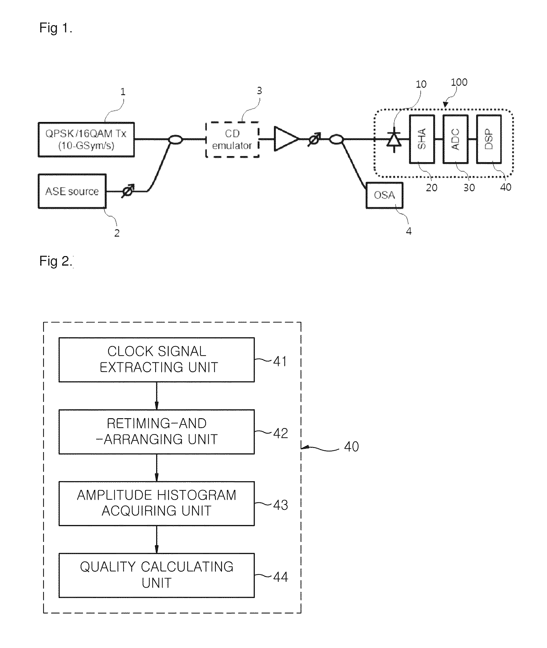
[0042]FIG. 1 is a schematic view for explaining an optical signal quality monitoring apparatus using a software-based synchronized amplitude histogram according to an embodiment of the present invention. An optical signal quality monitoring apparatus 100 according to the present invention includes an optical detector 10, an asynchronous sampling unit and a digital signal processor (DSP) 40.

[0043]The optical detector 10 serves to directly receive an optical signal modulated in an optical path and to convert the optical signal to an electric signal. In the present embodiment, it is preferred that the optical signal is one of an M-ary PSK (M-ary Phase-Shift Keying) signal, an M-ary DPSK (M-ary Differential Phase-Shift Keying) ...


PUM


Abstract

An optical signal quality monitoring apparatus includes an optical detector for directly receiving an optical signal modulated in an optical path and converting the optical signal to an electric signal, an asynchronous sampling unit for asynchronously sampling the electric signal of the optical detector at a reduced speed, and a digital signal processor for monitoring an optical signal quality by finding a synchronized amplitude histogram of data sampled in the asynchronous sampling unit. An optical signal quality monitoring method includes (a) a step of allowing an optical detector to directly receive a modulated optical signal and to convert the optical signal to an electric signal; (b) a step of allowing an asynchronous sampling unit to asynchronously sample the electric signal; and (c) a step of allowing a digital signal processor to monitor an optical signal quality by generating a synchronized amplitude histogram of sampled data.

Description

FIELD OF THE INVENTION[0001]The present invention relates to a method for monitoring a transmission quality of an optical signal and, more particularly, to a method and apparatus for monitoring a quality of an optical signal by acquiring a software-based synchronized amplitude histogram and analyzing the synchronized amplitude histogram.BACKGROUND OF THE INVENTION[0002]In recent years, a high-level modulation signal such as a quadrature phase-shift keying (QPSK) signal or a quadrature amplitude modulation (QAM) signal is extensively used to increase a transmission capacity per optical fiber.[0003]In order to efficiently manage a next-generation optical network in which the high-level modulation signal is widely used, there is a need to directly monitor a quality of an optical signal in an optical layer. To this end, Korean Registered Patent Publication No. 10-0553814 (published on Feb. 14, 2006) discloses a method for checking the distortion of an optical signal based on a data dist...

Claims


Application Information

Patent Timeline
Patent Type & Authority Patents(United States)
IPC IPC(8): H04B10/079
CPCH04B10/07953
Inventor CHUNG, YUN CHURCHOI, HYEOK GYUCHANG, JUN HO
Owner KOREA ADVANCED INST OF SCI & TECH
Why Eureka
Try Eureka