Supercharge Your Innovation With Domain-Expert AI Agents!

Apparatus and method for determining the spatial position and velocity vector of a spherical projectile

a technology of spatial position and velocity vector, applied in the direction of measurement devices, devices using time traversed, instruments, etc., can solve the problems of affecting the effectiveness of curve ball analysis, and limiting the usefulness of information, so as to improve the accuracy of position, velocity and trajectory, and the effect of inexpensive construction

Inactive Publication Date: 2015-10-13
STEFFL LEO THOMAS
View PDF22 Cites 7 Cited by
  • Summary
  • Abstract
  • Description
  • Claims
  • Application Information

AI Technical Summary

Benefits of technology

The device described in this patent meets the goal of providing more complete information and improving accuracy for position, velocity, and trajectory. It is easy to use, made up of readily available components, and is affordable to construct.

Problems solved by technology

However, this approach is prohibitively expensive for many applications.
This limits the usefulness of the information.
For example, since the effectiveness of a baseball pitch (such as a breaking ball) is almost entirely based on the non-linear characteristics of the flight path, the assumption of a linear trajectory results in information that is of little value for analyzing curve ball effectiveness.

Method used


Image

  • Apparatus and method for determining the spatial position and velocity vector of a spherical projectile
  • Apparatus and method for determining the spatial position and velocity vector of a spherical projectile
  • Apparatus and method for determining the spatial position and velocity vector of a spherical projectile

Examples


Embodiment Construction

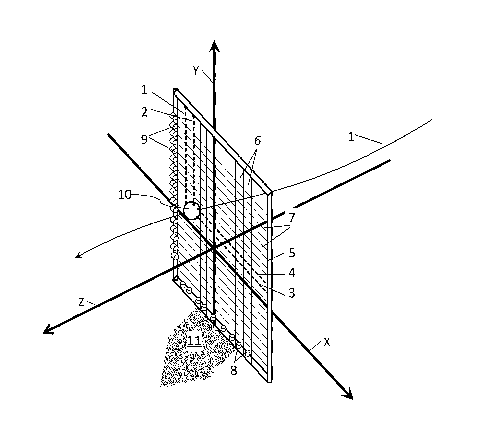
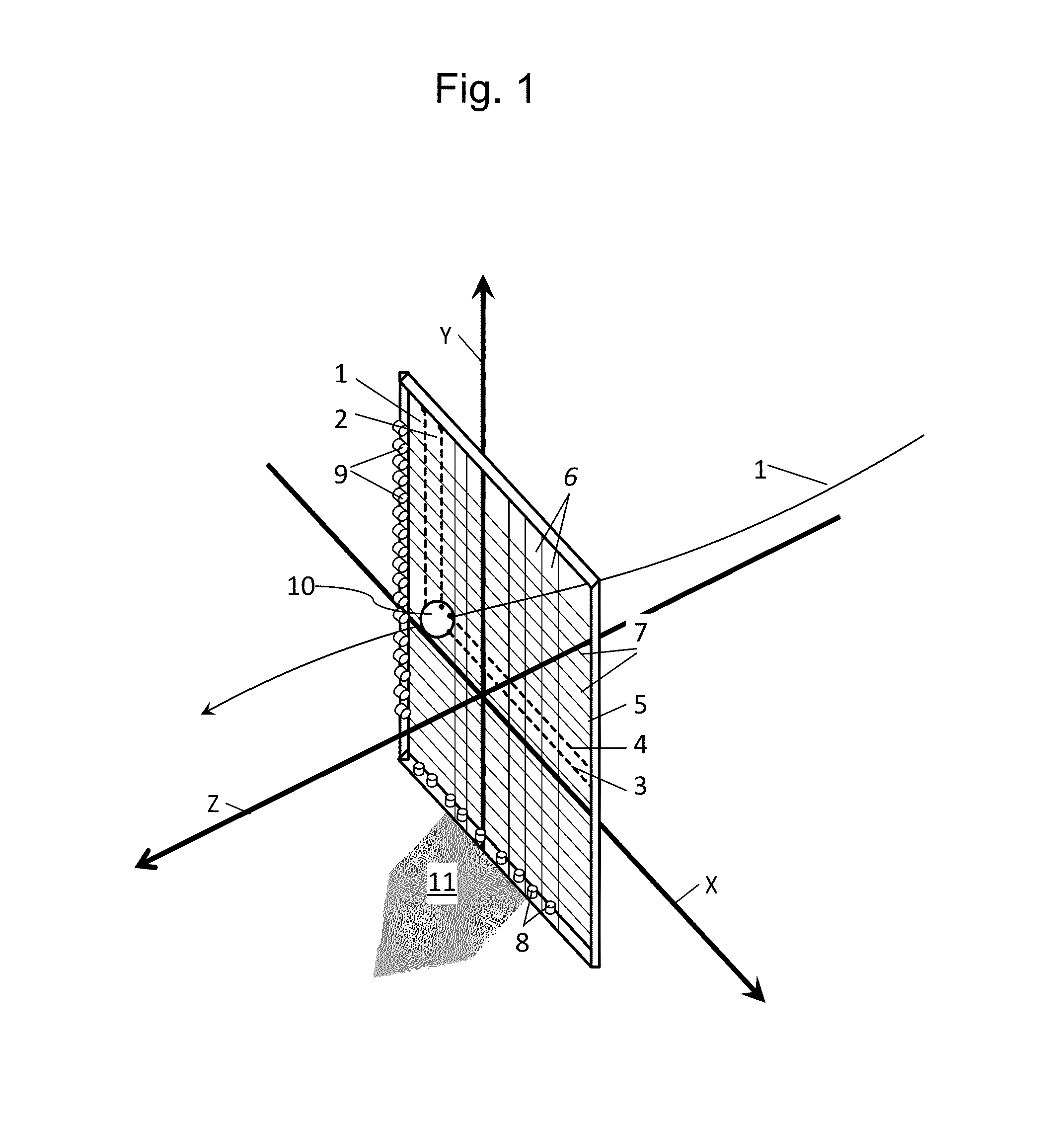
[0020]FIG. 1 shows a view of a spherical object 10 as it moves on a trajectory 1 toward a point of interest, in this case Home Plate 11. At the front edge of Home Plate, are located two Light Beam Arrays 5. Each Light Beam Array, hereafter referred to as an LBA, contains a beam projecting means (which emits a plurality of parallel beams of light) and a beam receiving means (which detects the obstruction of the beams of light).

[0021]FIG. 1 projecting means 6 is detected by receiving means 8 within the first LBA and projecting means 7 is detected by receiving means 9 within the second LBA.

[0022]The beam projecting means contains semiconductor emitters, such as laser diodes, as the light sources which emit a plurality of light beams sufficient in power to be detected by the semiconductor receivers. The beam receiving means comprises semiconductor receivers, such as photo diodes. The ray projecting means and receiving means are spaced, so that a minimum of two beams are obscured by the ...


PUM


Abstract

A spherical object is detected as it passes through an array of planer light beams and associated detectors. The construction of the apparatus is such that at least 4 planar light beams are obscured by the passing object, two parallel beams in one direction and two parallel beams in a second direction. The apparatus records the time at which each affected light beam is obstructed by the passing object. The apparatus then calculates the spatial position, velocity and trajectory of the object.

Description

BACKGROUND OF THE INVENTION[0001]This invention relates generally to devices for measuring the trajectory or flight path of a projectile. More specifically, it relates to systems using an array of light beams to determine the position, velocity and trajectory of a sphere or ball, such as a baseball as it passes through the Strike Zone.[0002]Devices for determining the velocity and position of a ball are numerous in the art. These devices are typically used in sports training or sports games including especially baseball and golf. In the game of golf, such devices are often used to determine the flight path of the ball. In the game of baseball, such devices are frequently used to determine ball location or ball speed at the Strike Zone.[0003]The inventions in the art can be grouped into several different categories depending on the technologies used. One method prevalent in the art uses radar systems. Another common method is the use of cameras and associated image processing. Ultras...

Claims


Application Information

Patent Timeline
Patent Type & Authority Patents(United States)
IPC IPC(8): G01P3/36G01B11/14G01P3/68G01B11/00
CPCG01B11/14G01P3/685G01B11/002
Inventor STEFFL, LEO THOMAS
Owner STEFFL LEO THOMAS
Features
  • R&D
  • Intellectual Property
  • Life Sciences
  • Materials
  • Tech Scout
  • Unparalleled Data Quality
  • Higher Quality Content
  • 60% Fewer Hallucinations
Learn More