Selectively controllable electromagnetic shielding

a technology of electromagnetic shielding and selective control, applied in the field of selective control, can solve the problems of increasing stray electromagnetic fields, affecting the safety of users, and unable to achieve the desired positional freedom of systems, etc., and achieves the effects of removing the shielding properties, high permeability, and sufficient strength

Active Publication Date: 2015-10-13
PHILIPS IP VENTURES BV
View PDF18 Cites 7 Cited by
  • Summary
  • Abstract
  • Description
  • Claims
  • Application Information

AI Technical Summary

Benefits of technology

[0008]The present invention provides a selectively controllable electromagnetic shield. In one embodiment, the present invention provides an electromagnetic shield and a mechanism for selectively generating an aperture in the shield. The mechanism for selectively generating an aperture in the shield may be a magnetic field source that generates a magnetic field of sufficient strength to substantially saturate all or a portion of the shield, thereby essentially temporarily removing its shielding properties. For example, a permanent magnet or DC electromagnet may be used to selectively saturate the shield. In its un-saturated state, the magnetic shield has a high permeability so that it draws the electromagnetic field into itself and functions as a flux path for the magnetic field. In effect, the shield directs the flow of much of the magnetic field through the shield so that the amount of the field passing from one side of the shield to the other is dramatically reduced. Once saturated (in the presence of an external magnetic field), the permeability of the shield is substantially reduced so that the magnetic field lines are no longer drawn into the shield to the same degree. As a result, once saturated, the effectiveness of the shield in the saturated region is reduced and a substantially greater amount of the electromagnetic field may flow through or around the shield in the region saturated by the magnet.
[0014]Similarly, the remote device may include a supplemental shield, which may be disposed between the secondary and the electronics of the remote device. The supplemental shield may help to limit flow of the magnetic field to the electronics of the remote device and to elements outside the remote device. The supplemental shield of the remote device may be configured so that it is not saturated by the magnetic field used to open an aperture in the selectively controllable magnetic shield. This configuration may be achieved by material selection, material thickness, geometric placement of the shield within the assembly, and other factors. As a result, the supplemental shield of the remote device may continue to be an effective shield even when an aperture has been opened.
[0017]The present invention can be used in a wide variety of applications, including applications that relate to transmitting electromagnetic fields, such as wireless power and wireless communications, to consumer electronics devices, computers, headsets, electric appliances, electric tools, vehicles (e.g. passenger, commercial and military vehicles) and military devices. In the context of wireless power transfer, the present invention can be used to provide a large charging surface with a wide range of positional freedom for placing a remote device during power transfer / charging. For example, the selectively controllable shielding can be use to focus and control magnetic field transmission, such as inductive wireless power transfer, over a broad surface. By having a selective magnetic aperture in a charger surface a single, larger primary coil can be used to transmit to one or multiple secondary coils while limiting parasitic losses. Embodiments that incorporate localized saturation will largely contain the magnetic field except where intended (e.g. regions where the shield has been adequately saturated). One benefit of embodiments that incorporate localized saturation is that they allows lossy items placed on the charging surface away from the aperture to not materially impact parasitic losses as they would typically with standard pads or field areas. In embodiments that combine selectively controllable shielding with supplemental shielding, the present invention provides the ability to fully shield a device (or a portion of a device) while at the same time allowing a window in the shield to be selectively opened when and where it is desirable to allow magnetic field penetration. As can be appreciated, in some embodiments, the present invention may provide a mechanism in which two of the primary concerns—spatial freedom and magnetic field broadcast—can be handled and controlled while transferring power efficiently, by the use of selective saturation of the shield (e.g. a magnetic ferrite flux-guide) to allow power transmission substantially only at the particular location(s) (e.g. a region on a transmitter pad) where it is needed by a receiver (e.g. a secondary coil). The shield can act both as a flux shield by protecting excess flux from being broadcast into the surroundings, but also as a flux guide to limit flux leakage and increase power transfer efficiency.

Problems solved by technology

Although providing efficient power transfer, these types of systems lack the desired amount positional freedom that might be desired in some applications.
Although providing increased spatial freedom, the large primary coil can increase stray electromagnetic fields and dramatically increase parasitic losses.
For example, stray electromagnetic fields may cause metal within the remote device to heat, thereby heating the remote device.
These types of system may include relatively complex mechanical and / or electro-mechanical systems that can significantly increase cost and create reliability issues.
For example, mechanical assemblies involve moving parts tend to be more likely to fail than purely electronic systems.
In addition to cost and reliability issues, motorized systems require time for the primary to be moved into the appropriate position.
Manually adjusted systems require human intervention and therefore may not be as convenient as they would be if the remote device could be placed randomly within a large zone and forgotten.
Array-type systems require multiple coils and therefore can be more expensive to implement.
They may also involve relatively complex controls, such as additional electronic hardware, for determining which coil(s) in the array to energize and for selectively switching the coils to the proper configuration to provide power to the remote device.
However, it is believed that inadequate discussion has been directed toward the issue of precise delivery of the magnetic flux for inductive power transfer, as is the case in most transmission pads.
This problem of electromagnetic field broadcast has traditionally been addressed using power electronics to shut down transmission during non-active periods, but even this technique has residual power being broadcast due to the presence of the communication circuits.
Furthermore, such a technique including single-coil transmission systems is generally only applicable to small surface area transmission pads, which do not power multiple devices at the same time.
In the case of wide surface area charging systems (delivery of power to multiple remote devices), the field broadcast challenges have gone largely undiscussed in literature that addresses multiple receiver transmission.
This is because shutting down the circuit at a particular location due to the removal of one remote device will deprive another remote device of power.
Conversely, if the electronic algorithm doesn't include shutdown of the system at one location when one or multiple devices are being charged, then a case of magnetic field broadcast into the surroundings can occur, with its adverse effects.

Method used


Image

  • Selectively controllable electromagnetic shielding
  • Selectively controllable electromagnetic shielding
  • Selectively controllable electromagnetic shielding

Examples


Embodiment Construction

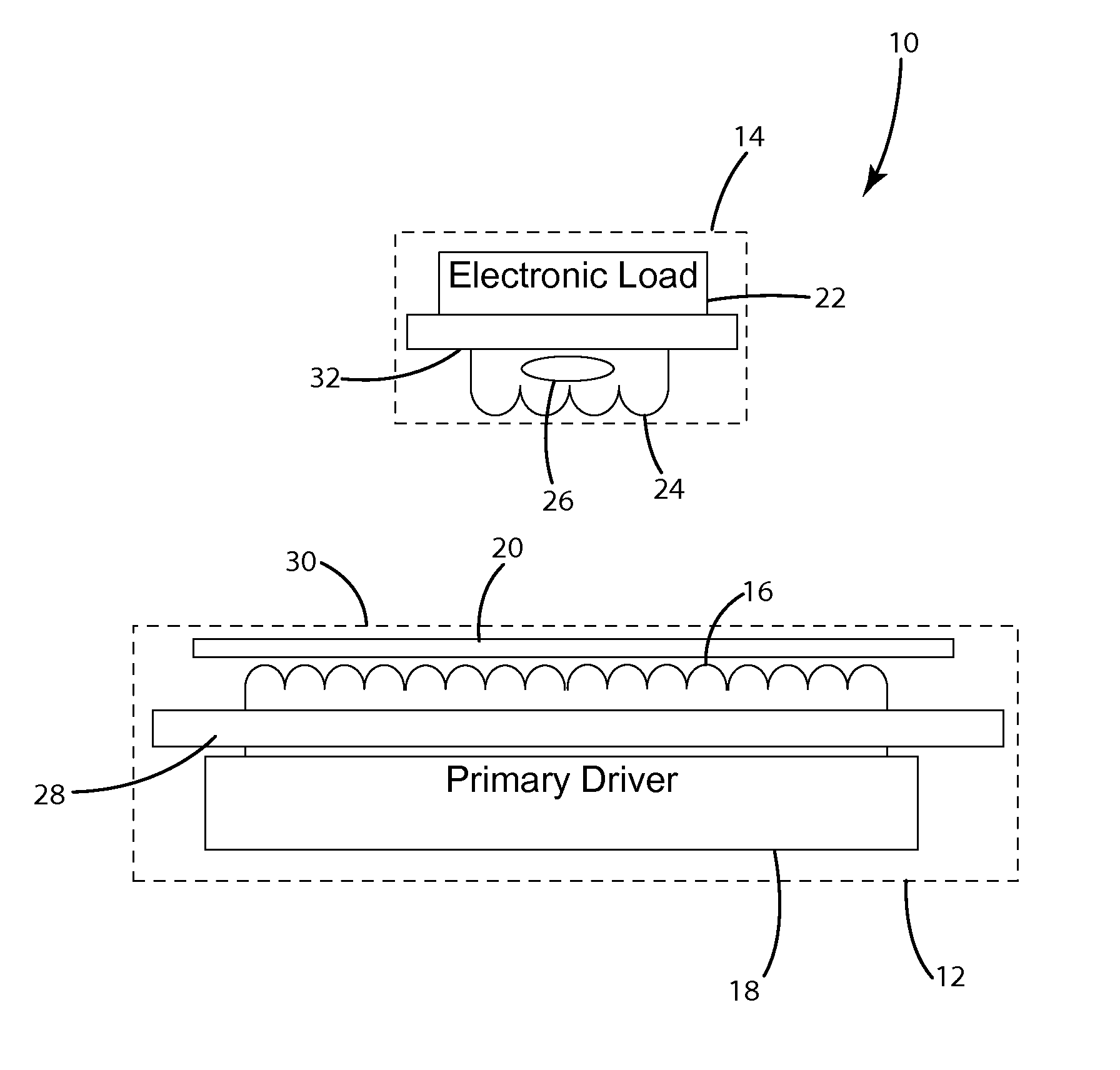
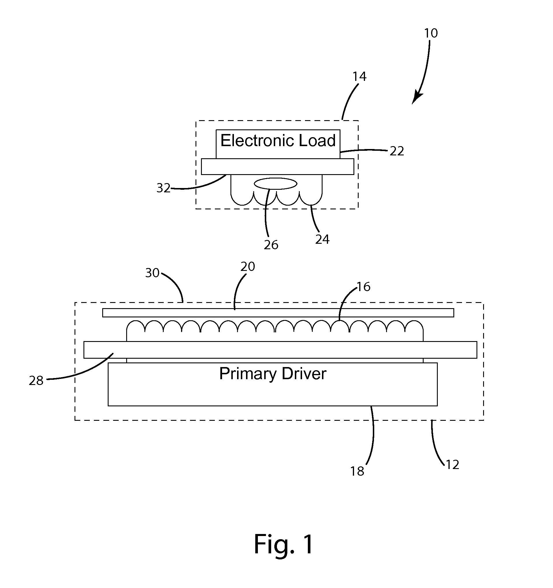
[0051]A wireless power supply system incorporating an embodiment of the present invention is shown in FIG. 1. The wireless power supply system 10 generally includes a wireless power supply 12 and a remote device 14. The wireless power supply 12 of this embodiment includes a primary coil 16, a primary driver 18 and an intermediate magnetic shield 20. In use, the primary driver 18 applies an alternating signal to the primary coil 16 to produce a magnetic field. The remote device 14 of this embodiment includes an electronic load 22, a secondary coil 24 and a permanent magnet 26. When in the presence of an appropriate magnetic field, a current is induced in the secondary coil 24 to provide power for the electronic load 22. The induced power may be used to charge the remote device 14 and / or to directly power the remote device 14. The illustrated intermediate shield 20 is a magnetic shield that can be selectively saturated by a magnetic field to provide an aperture in the shield. In a non...


PUM

PropertyMeasurementUnit
electromagnetic fieldaaaaaaaaaa
permeabilityaaaaaaaaaa
magnetic fieldaaaaaaaaaa

Abstract

A selectively controllable electromagnetic shield having an electromagnetic shielding material and a mechanism for selectively generating an aperture in the shield. The mechanism for selectively generating an aperture may be a magnetic field source that generates a magnetic field of sufficient strength to substantially saturate all or a portion of the shielding material. For example, a permanent magnet or DC electromagnet may be used to selectively saturate the shield. In its un-saturated state, the magnetic shield has a high permeability and functions as a flux path for the magnetic field. Once saturated, the permeability of the shield is substantially reduced so that the magnetic field lines are no longer drawn into the shield to the same degree. As a result, once saturated, a substantially greater amount of the electromagnetic field may flow through or around the shield in the saturated region.

Description

[0001]The present invention relates to electromagnetic shielding and more particularly to systems and methods for providing selective control over electromagnetic shielding.BACKGROUND[0002]In recent years, there has been a widespread increase in efforts to implement wireless power transfer systems in both commercial and residential settings. Wireless power systems offer the promise of eliminating power / charging cords for a wide range of electrically powered devices, including not only handheld electronics, such as cell phones, media players, wireless headsets and personal digital assistants, but also higher power devices, such as appliances, tools and electric vehicles. Efficient inductive power transfer has become an area of increasing scientific interest as it can solve some problems associated with traditional wired or contact power transmission. These include but are not limited to corrosion, mechanical friction, clutter and impracticality in places like underwater and subterran...

Claims


Application Information

Patent Timeline
Patent Type & Authority Patents(United States)
IPC IPC(8): H04B5/00B60L11/18H01F27/36H05K9/00H01F38/14H02J7/02
CPCH05K9/0088B60L11/182H01F38/14H04B5/00H05K9/002H01F27/362Y02T90/122Y02T90/14Y10T29/49002Y02T10/7005H02J7/025Y02T10/7072B60L53/126B60L53/124H02J50/10H01F27/36Y02T10/70H01F27/366H02J50/70B60Y2200/24B60Y2200/14B60Y2200/11H02J50/80H02J50/12Y02T90/12
Inventor BAARMAN, DAVID W.STONER, JR., WILLIAM T.SCHWANNECKE, JOSHUA K.TURNER, KAITLYN J.MOES, BENJAMIN C.
Owner PHILIPS IP VENTURES BV
Why Eureka
Try Eureka