System and method for corneal pachymetry using plenoptic imaging

a plenoptic imaging and pachymetry technology, applied in the field of vision techniques, can solve the problems of inaccurate measurement, wrong patient prevention, and inability to perform procedures, and achieve the effect of accurately determining the corneal thickness of the eye and improving the accuracy of corneal measurements

Active Publication Date: 2015-10-20
AMO DEVMENT
View PDF25 Cites 3 Cited by
  • Summary
  • Abstract
  • Description
  • Claims
  • Application Information

AI Technical Summary

Benefits of technology

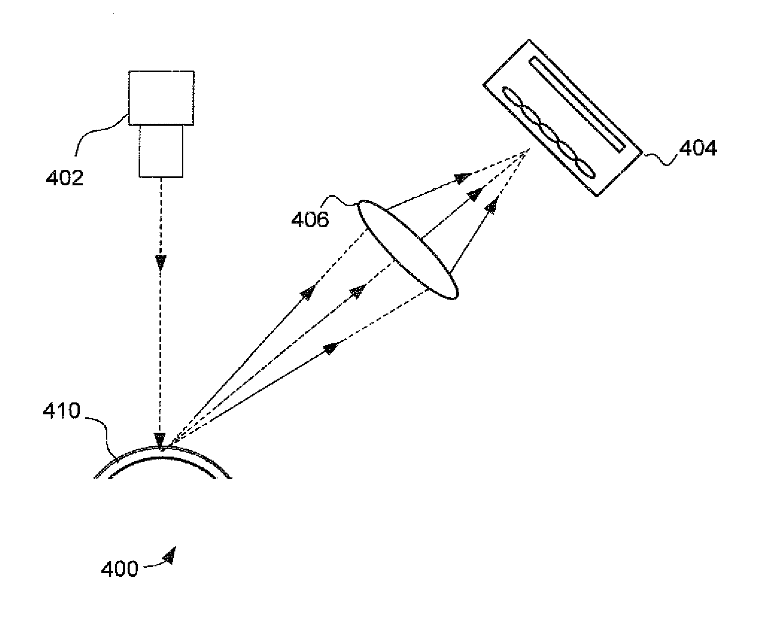
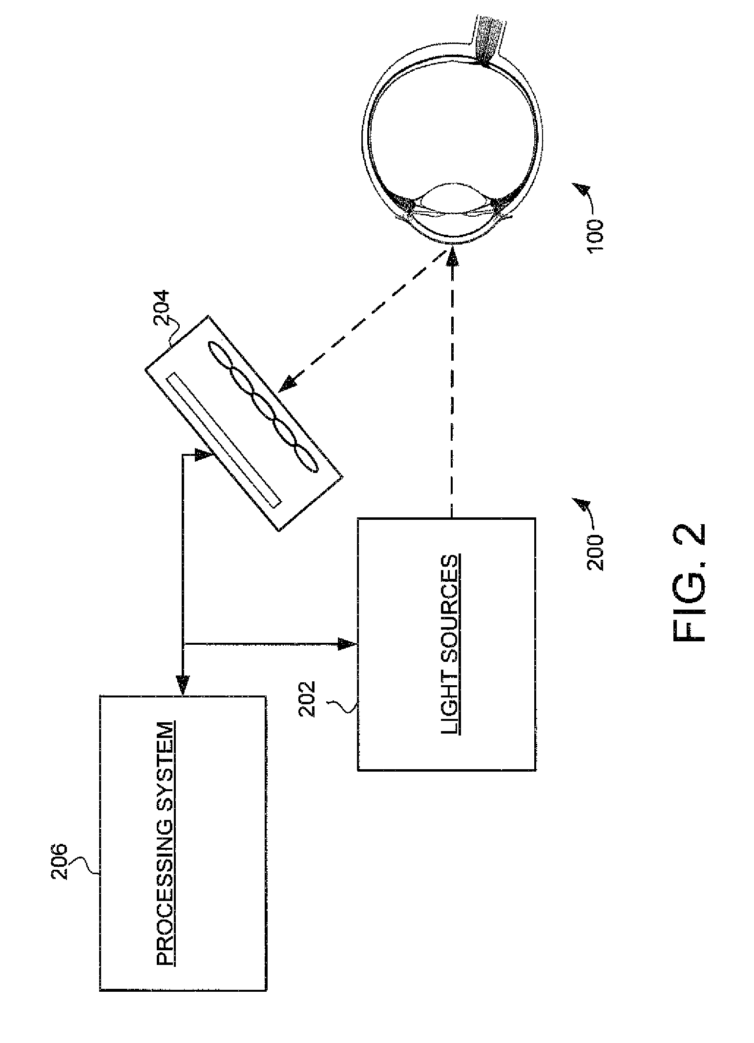
[0006]Embodiments of the present invention generally provide improved systems and methods for corneal pachymetry. These systems and methods can be used to improve the accuracy of corneal measurements that are used for a wide variety of different ophthalmic procedures, including various types of ocular surgeries. One embodiment provides a system and method for corneal pachymetry using a plenoptic detector. For example, a corneal pachymetry system can comprise a light source, a plenoptic detector and a processing system coupled to the plenoptic detector. The light source is configured to illuminate the cornea of the eye, and the plenoptic detector is positioned at an angle relative to the eye. The plenoptic detector is configured to receive an image of the light source reflected from the cornea and generate plenoptic image data representing the images. The processing system is coupled to the plenoptic detector and is configured to analyze the plenoptic image data to accurately determine the corneal thickness of the eye.
[0007]Thus, the system and method can determine corneal pachymetry using a plenoptic detector. The use the plenoptic detector for corneal pachymetry can provide accurate measurement of corneal thickness.

Problems solved by technology

That is, if the corneal thickness is not within a specified limit the procedure cannot be performed.
In those cases an inaccurate measurement can wrongly prevent patients from qualifying for the procedure.
Or conversely, an inaccurate measurement can wrongly allow patients to undergo the procedure.

Method used


Image

  • System and method for corneal pachymetry using plenoptic imaging
  • System and method for corneal pachymetry using plenoptic imaging
  • System and method for corneal pachymetry using plenoptic imaging

Examples


Embodiment Construction

[0016]The figures and descriptions of the present invention have been simplified to illustrate elements that are relevant for a clear understanding of the present invention, while eliminating, for the purpose of clarity and brevity, many other elements found in typical ophthalmic techniques, systems, methods, lenses, and implantable optic apparatuses. Those of ordinary skill in the art may thus recognize that other elements and / or steps are desirable and / or required in implementing the present invention. However, because such elements and steps are well known in the art, and because they do not necessarily facilitate a better understanding of the present invention, those elements and steps are not discussed. This disclosure is directed to all applicable variations, changes, and modifications known to those skilled in the art. As such, the following detailed descriptions are merely illustrative and exemplary in nature and are not intended to limit the embodiments of the subject matte...


PUM


Abstract

Embodiments described herein provide improved systems and methods for corneal pachymetry. These systems and methods can be used to improve the accuracy of corneal measurements that are used for a wide variety of different ophthalmic procedures. One embodiment provides a system and method for corneal pachymetry using a plenoptic detector. For example, a corneal pachymetry system can comprise a light source, a plenoptic detector and a processing system coupled to the plenoptic detector. The light source is configured to illuminate the cornea of the eye, and the plenoptic detector is positioned at an angle relative to the eye. The plenoptic detector is configured to receive an image of the light source reflected from the cornea and generate plenoptic image data representing the images. The processing system is coupled to the plenoptic detector and is configured to analyze the plenoptic image data to accurately determine the corneal thickness of the eye.

Description

CROSS-REFERENCES TO RELATED APPLICATIONS[0001]This application claims priority to U.S. provisional application No. 61 / 793,510 filed on Mar. 15, 2013, the entire contents of which are incorporated herein by reference.TECHNICAL FIELD[0002]Embodiments of the present invention generally relate to vision techniques, and particularly to techniques for corneal pachymetry.BACKGROUND OF THE INVENTION[0003]Many modern ophthalmic surgical procedures require accurate measurements of the eye. For example, measurements of aberrations of the eye are important for the diagnosis and treatment of visual defects and acuity. Furthermore, there are a growing number of ways that aberrations can be corrected using both surgical and non-surgical means. Many of these methods rely on accurate, precise measurements of the whole ocular system so that patients may be screened, the corrective means applied and tested, and follow up care provided as appropriate.[0004]One important type of ocular measurement is re...

Claims


Application Information

Patent Timeline
Patent Type & Authority Patents(United States)
IPC IPC(8): A61B3/14A61B3/10A61B3/00
CPCA61B3/1005A61B3/14
Inventor RAYMOND, THOMAS D.COPLAND, RICHARD J.
Owner AMO DEVMENT
Why Eureka
Try Eureka