Paste dispenser for applying paste containing fillers using nozzle with pin and application method using the same

a dispenser and filler technology, applied in the field of filler dispensers, can solve the problems of faulty application, unstable amount of application, applicator malfunction, etc., and achieve the effect of not dripping and stable application

Active Publication Date: 2015-10-20
PANASONIC INTELLECTUAL PROPERTY MANAGEMENT CO LTD
View PDF70 Cites 13 Cited by
  • Summary
  • Abstract
  • Description
  • Claims
  • Application Information

AI Technical Summary

Benefits of technology

[0010]An object of the present invention is to provide a paste applicator and a paste application method which can stably apply even a small amount of paste, which contains a filler such as solder powder, to a target object such as a substrate.
[0011]Another object of the present invention is to provide a paste applicator and a paste application method which can satisfactorily form bumps on a target object such as a substrate.
[0013]A paste application method according to the present invention includes the steps of: placing a nozzle which has a discharge opening formed on the end, is disposed above a target object with the discharge opening placed at the bottom, and is filled with paste, the nozzle being placed such that the nozzle is relatively moved toward and away from the target object and the discharge opening comes close to the target object; applying the paste to the target object by bringing a pin close to the discharge opening while the discharge opening of the nozzle comes close to the target object and bringing the paste into contact with the target object, the paste being protruded to the target object so as not to drip from the discharge opening; and separating the paste in contact with the target object from the paste around the discharge opening by moving the pin away from the discharge opening in a relative movement increasing a distance between the nozzle and the target object.
[0027]Hence, the paste applicator can stably apply a small amount of the paste, which contains a filler such as the solder powder, to the target object such as a substrate.

Problems solved by technology

However, when the paste 11 contains solder powder, the paste applicator 10 may cause faulty application or an unstable amount of application.
As a result, the applicator may have a malfunction or a failure and the paste 11 may not be applied onto the target object 12, causing faulty application.

Method used


Image

  • Paste dispenser for applying paste containing fillers using nozzle with pin and application method using the same
  • Paste dispenser for applying paste containing fillers using nozzle with pin and application method using the same
  • Paste dispenser for applying paste containing fillers using nozzle with pin and application method using the same

Examples


first embodiment

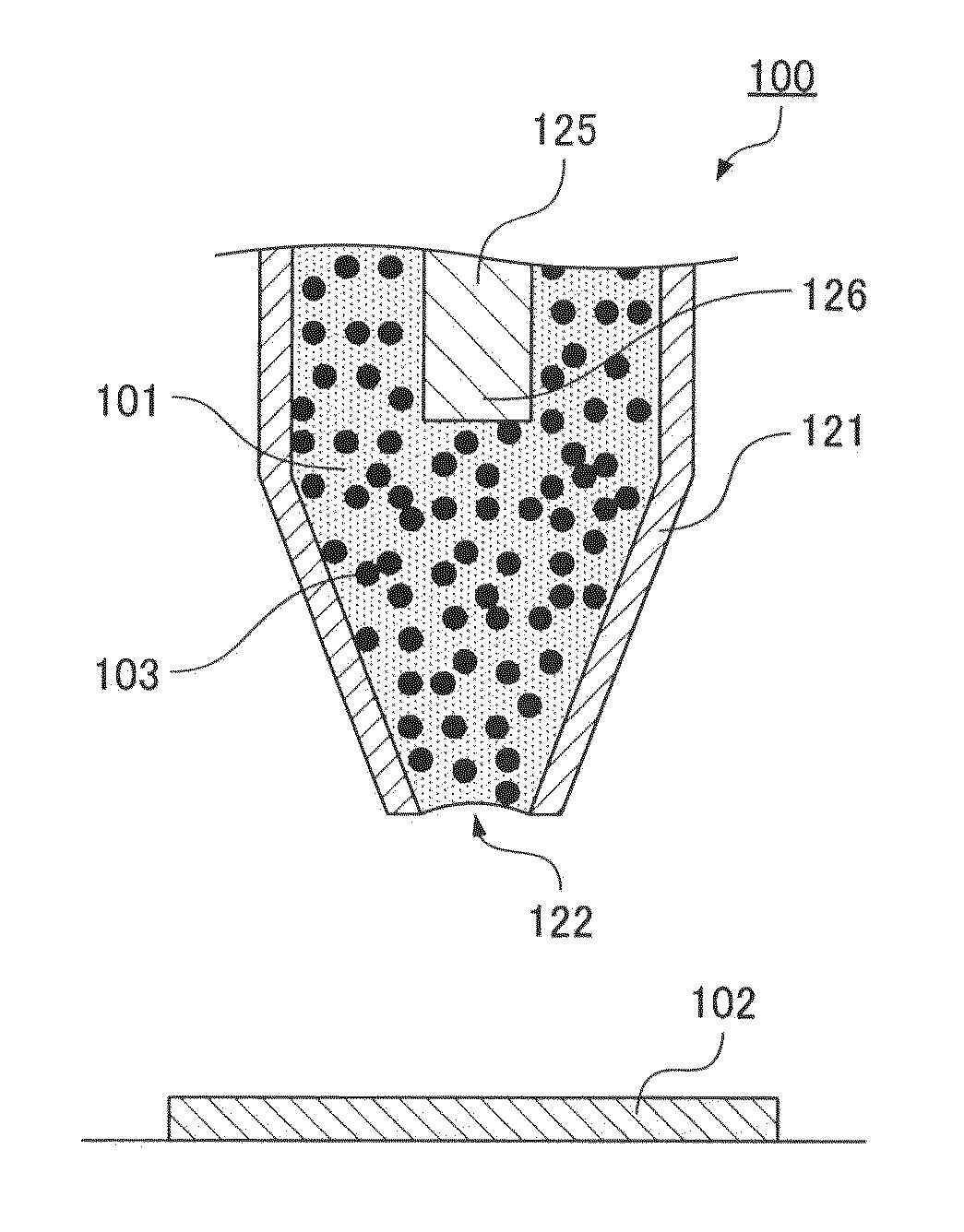
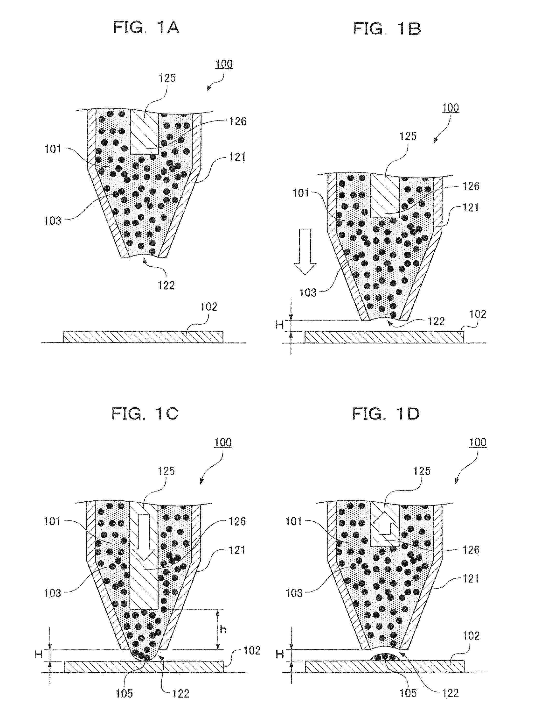
[0053]As shown in FIGS. 1A to 1D, a paste applicator 100 is a device for discharging a small amount of paste 101.

[0054]As shown in FIG. 1A, a discharge opening 122 is formed on the end of a nozzle 121. The nozzle 121 is disposed above a target object 102 with the discharge opening 122 placed at the bottom. The paste 101 has been put into the nozzle 121. The paste 101 contains solder powder 103. In the paste 101 having been put into the nozzle 121, an end 126 of a vertically disposed pin 125 is placed.

[0055]First, as shown in FIG. 1B, the nozzle 121 is moved down until the discharge opening 122 is disposed within a distance H from the surface of the target object 102. The discharge opening 122 is stopped within the distance H from the surface of the target object 102; meanwhile, the pin 125 is moved down as shown in FIG. 1C, the paste 101 is protruded from the discharge opening 122 to the outside of the nozzle 121, and an end 105 of the protruded paste 101 is brought into contact wit...

second embodiment

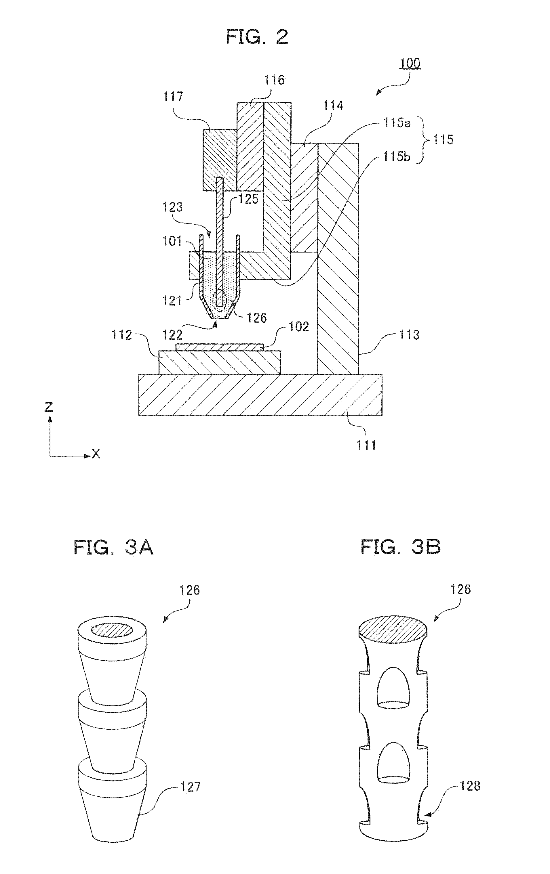
[0085]FIG. 5 shows an example of the formation of a solder bump. FIG. 5 shows a nozzle 401, a pin 405, a target object 408, heaters 409a and 409b acting as heating sections, and a gas port 411. A driving section for the ascent, descent, and horizontal movements of the nozzle 401, the pin 405, the target object 408, and so on is similar to the paste applicator 100 of FIG. 2 illustrated in the first embodiment.

[0086]The nozzle 401 and the pin 405 are similar to the nozzle 121 and the pin 125 of the first embodiment. Further, the nozzle 401 and a driving mechanism for moving the pin 405 and the target object 408 relative to the nozzle 401 are similar to the nozzle and the mechanism of FIG. 2. The second embodiment is different from the first embodiment only in the provision of a device and the like for releasing inert gas g from around a discharge opening 400 of the nozzle 401.

[0087]Paste 200 put into the nozzle 401 is composed of solder powder 200a contained in resin 200b. By heating ...


PUM

PropertyMeasurementUnit
viscosityaaaaaaaaaa
particle diameteraaaaaaaaaa
diameteraaaaaaaaaa

Abstract

A pin (125) is moved down in a nozzle (121), the end of paste (101) protruded from the discharge opening (122) of the nozzle (121) to a target object (102) is brought into contact with the target object (102), and the pin (125) is moved away from the discharge opening (122) to divide the paste in contact with the target object.

Description

FIELD OF THE INVENTION[0001]The present invention relates to a paste applicator for stably applying a small amount of paste to a target object, and a paste application method.BACKGROUND OF THE INVENTION[0002]In recent years, electronic equipment with a smaller size, a smaller thickness, and a higher density has been demanded. In order to manufacture electronic equipment satisfying such a demand, a method of mounting small electronic components on a substrate by flip-chip packaging has been used. As electronic components have been reduced in size, bumps have been also reduced in size with smaller pitches. Hence, it has been necessary to stably apply a small amount of solder paste to small bumps with small pitches.[0003]Japanese Patent Laid-Open No. 2006-320795 discloses a discharge device for discharging small droplets having even particle diameters into a retained solution, though the device does not apply paste used for the mounting of electronic equipment.DISCLOSURE OF THE INVENTI...

Claims


Application Information

Patent Timeline
Patent Type & Authority Patents(United States)
IPC IPC(8): B05C1/00B05C11/00B05C11/10B23K1/00B23K3/06H05K3/34C23C14/54B05D3/04G01F11/20G01F11/00B05C5/02B05C9/02B05D1/26
CPCB05C5/0225B23K1/0016B23K3/0692H05K3/3484B05C11/1034B05C5/02B05C5/0212B05C9/02B05D1/26B05D3/0466B23K2201/40G01F11/00H05K2203/0126B05C1/027B23K2101/40H05K3/3485
Inventor KOYAMA, MASAYOSHITSUKAHARA, NORIHITOKOMYOJI, DAIDO
Owner PANASONIC INTELLECTUAL PROPERTY MANAGEMENT CO LTD
Why Eureka
Try Eureka