Axial passive magnet bearing system

a passive magnet bearing and axial bearing technology, applied in the direction of bearings, shafts and bearings, dynamo-electric machines, etc., can solve the problems of reducing the need for performance maintenance and extending the useful life of the whole system, so as to reduce friction, loss, vibration, noise

Active Publication Date: 2015-10-20
CHUNG YUAN CHRISTIAN UNIVERSITY
View PDF12 Cites 0 Cited by
  • Summary
  • Abstract
  • Description
  • Claims
  • Application Information

AI Technical Summary

Benefits of technology

[0010]By adjusting the relative positions and the connections between these structures, also by adjusting the magnetic force (attractive force or exclude force) between the two magnets, the force applied on the mechanical bearing may be decreased. Thus, at least the lose and the deformation of the mechanical bearing may be decreased, also the required performance maintenance may be decreased and the useful lifetime of the whole system may be elongated. For example, in a vertical mechanism where the first structure is positioned over the second structure, the combination of the third structure, the fourth structure and the two magnets may allow the magnetic force being opposite to the gravity force applied to both the mechanical bearing and the second structure, so that the net force applied on the mechanical bearing is decreased.
[0011]With the advance of material technology, many permanent magnet materials are used in many different commercial products. For example, some candidate materials of the permanent magnet materials include, but not limited to, ferrite magnet, Al—Ni—Co alloy, Sm—Co alloy, Ne—Fe—B alloy, and so on. Hence, each magnet of the axial passive magnet bearing system may be made of commercial permanent magnet material(s), and satisfy the requirements of longer lifetime, higher magnetic flux, better stability, more uniform magnetic field, and so on.
[0012]Other preferred embodiments also are axial passive magnet bearing systems. The main characteristic of these embodiment is the usage of the magnetic force between different magnets for decreasing the net force applied to the mechanical bearing positioned between the first structure and the second structure, so as to reduce friction, loss, vibration, noise and so on. For different embodiments, the relative positions and the mechanical connections between the third / fourth structures and the first / second structures may be different, also the relative positions and the mechanical connections between the first / second magnets and the third / fourth structures may be different. Hence, the axial passive magnet bearing system may be flexibly adjusted, and are utilized by different mechanisms.

Problems solved by technology

Thus, at least the lose and the deformation of the mechanical bearing may be decreased, also the required performance maintenance may be decreased and the useful lifetime of the whole system may be elongated.

Method used


Image

  • Axial passive magnet bearing system
  • Axial passive magnet bearing system
  • Axial passive magnet bearing system

Examples


Embodiment Construction

[0019]The detailed description of the present invention will be discussed in the following embodiments, which are not intended to limit the scope of the present invention, but can be adapted for other applications. While drawings are illustrated with some details, it is appreciated that the quantity of the disclosed components may be greater or less than that disclosed, except expressly restricting the amount of the components.

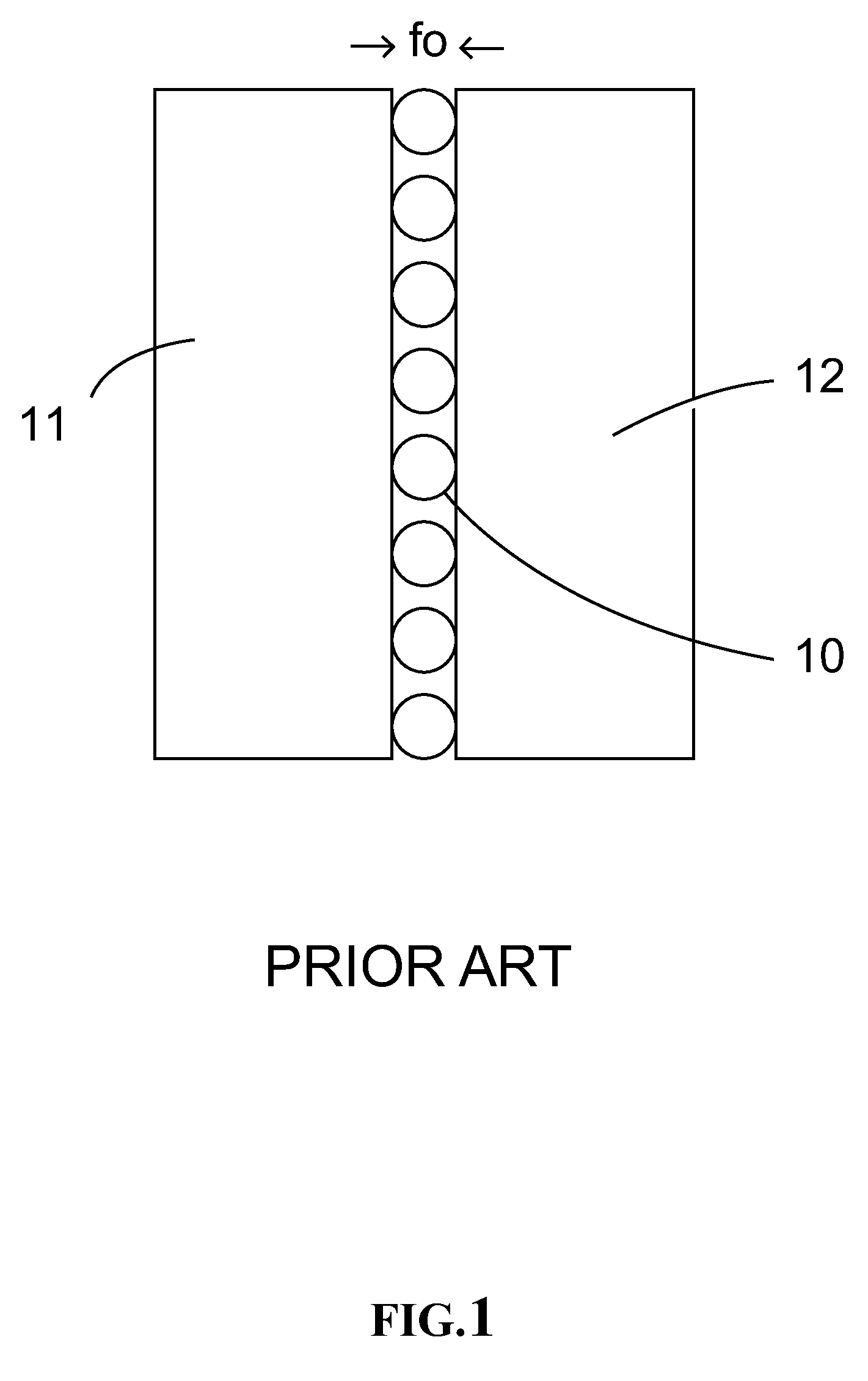
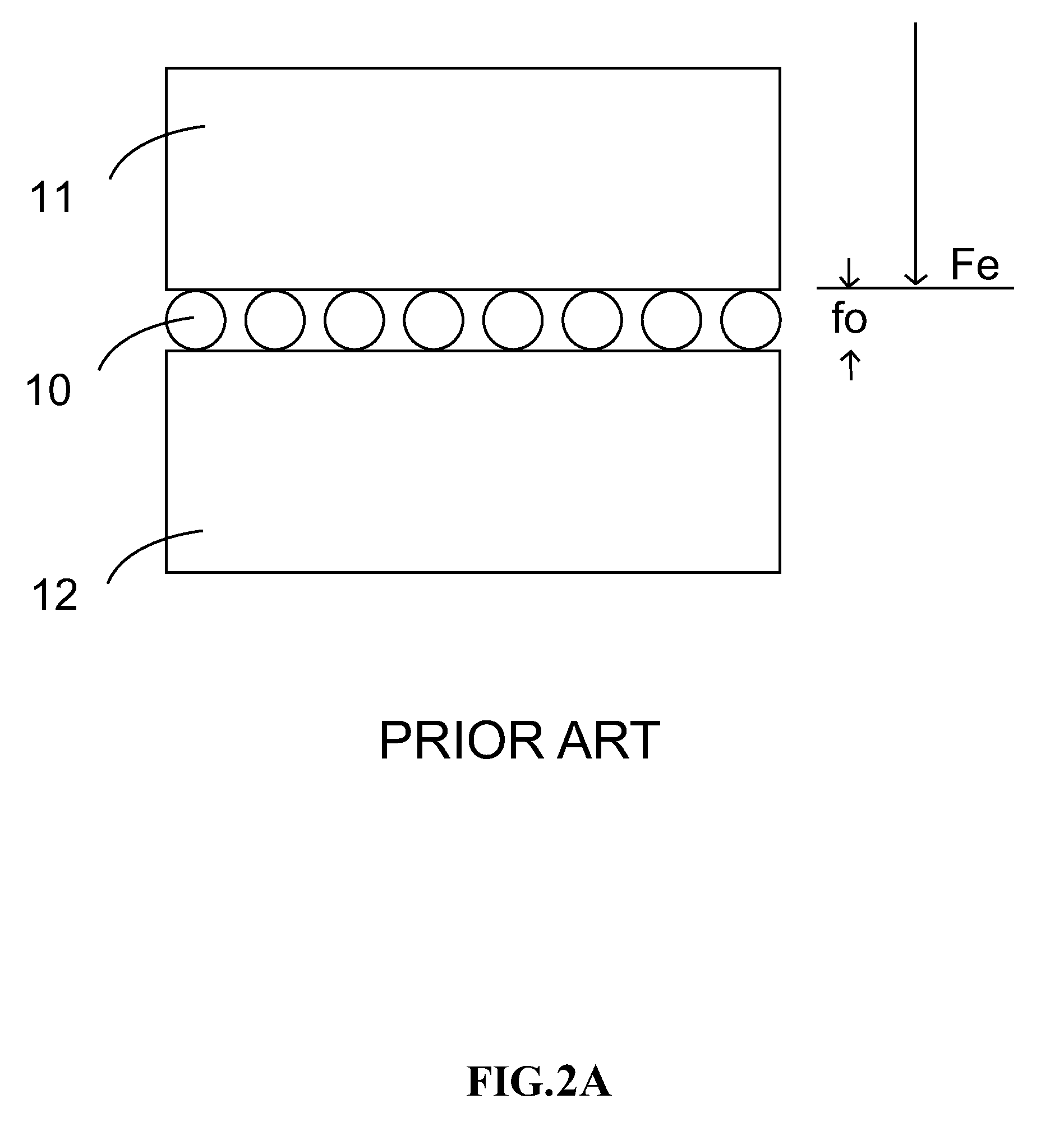
[0020]As shown on FIG. 1, for a mechanical bearing system, at least one mechanical bearing 10 is positioned between first structure 11 and second structure 12 along an axial direction, also mechanical bearing 10 mechanically contacts with both structures 11 / 12 which are separated from each other. Once first structure 11 and second structure 12 has relative motion, such as slide or rotation, mechanical bearing 10 may rotate and / or slide to provide an elastic support between first structure 11 and second structure 12 so as to reduce friction, vibration, noise, l...


PUM


Abstract

An axial passive magnet bearing system utilizes the friction-less characteristic of non-contact type permanent magnet bearing to minimize the disadvantages induced by frictions. For example, both the energy and material loses of the mechanical bearing. Two permanents magnet are made of permanent magnet materials and positioned over two opposite surfaces of two mechanical structures, where mechanical bearing(s) is located therebetween. Hence, the magnetic force between the two magnets can improve some disadvantages among the two mechanical structures and the mechanical bearings, such as friction and energy loss.

Description

BACKGROUND OF THE INVENTION[0001]1. Field of the Invention[0002]The present disclosure relates generally to axial passive magnet bearing system, and more particularly to axial passive magnet bearing system capable of reducing axial loading and energy loss induced by friction.[0003]2. Background of the Related Art[0004]The relative motion between different structures of a mechanism is very popular for industry and daily life. The bearing is popularly used to stable and support the action of the rotation axis when one or more of movement and / or rotation are required. For example, the ball bearing, the roller bearing and the needle bearing. Essentially, the bearing provides a rotation support between the rotator and the stator, so that the rotor indirectly contacts with the stator. Hence, the rotation and the movement of the bearing may reduce some disadvantages induced by the relative motion between the rotator and the stator, such as friction, vibration, noise, lose, and so on.[0005]...

Claims


Application Information

Patent Timeline
Patent Type & Authority Patents(United States)
IPC IPC(8): H02K7/09F16C32/04
CPCF16C32/0402F16C32/0412F16C32/0425Y02E10/725Y02E10/72
Inventor FAN, YI-HUALEE, YING-TSUNWANG, CHUNG-CHUNLIAO, YI-LIN
Owner CHUNG YUAN CHRISTIAN UNIVERSITY
Why Eureka
Try Eureka