Unlock instant, AI-driven research and patent intelligence for your innovation.

Connector

a technology of connecting rods and connectors, applied in the direction of coupling device connection, coupling parts engagement/disengagement, electrical apparatus, etc., can solve the problem of not being able to easily determine with the eyes whether the flat conductor is flat or not, and achieve the effect of reducing the number of operational works

Active Publication Date: 2015-10-20
ORMON CORP
View PDF87 Cites 9 Cited by
  • Summary
  • Abstract
  • Description
  • Claims
  • Application Information

AI Technical Summary

Benefits of technology

The present invention aims to provide a connector that allows for secure and easy connection of an inserted substrate, with minimal equipment requirements. The connector has an elastic holding function to ensure a proper connection, without the need for excessive force during installation. Additionally, the connector allows easy checking of the electrical connection through the position determining member. The technical effects of this invention include improved efficiency in assembly and connection, reduction of operational works, and improved reliability of the electrical connection.

Problems solved by technology

Furthermore, there is a problem that it cannot be easily determined with the eyes whether or not the flat conductor is made conductive.
With this configuration, not only a separate member for holding the movement member is made unnecessary, but also the smooth movement of the movement member may be caused by the elastic supporting.

Method used


Image

  • Connector
  • Connector
  • Connector

Examples


first embodiment

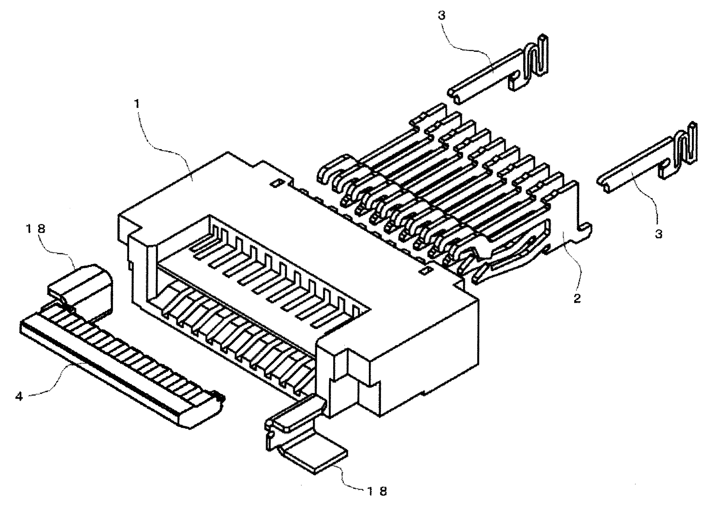
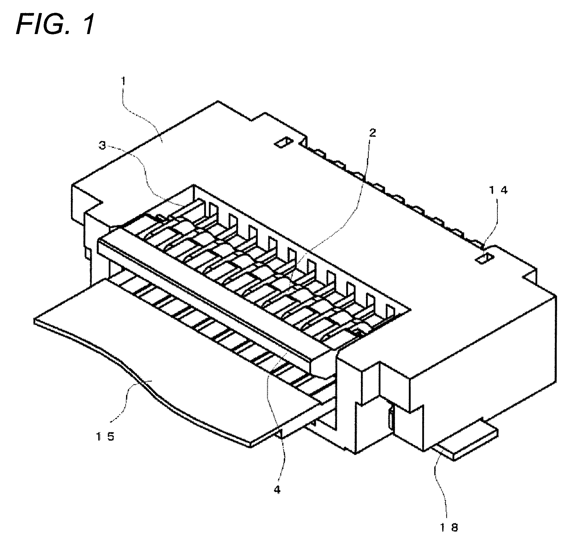
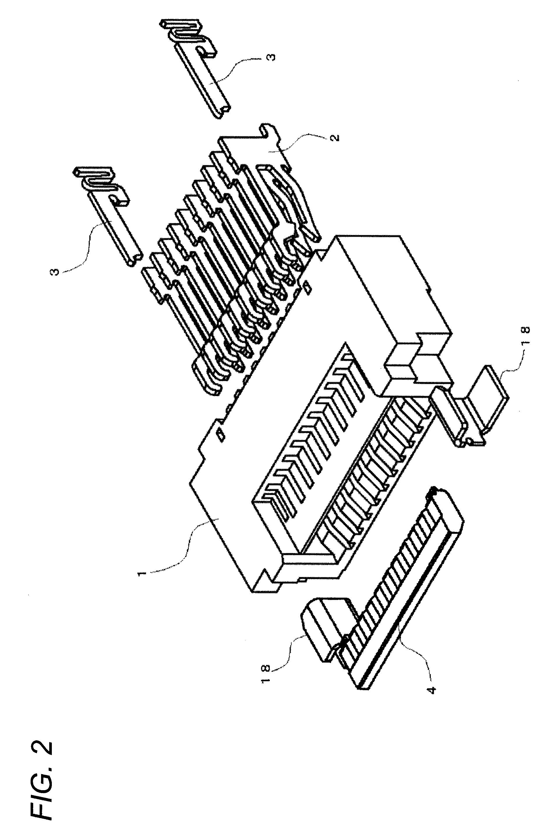
[0060]FIG. 1 is an overall view illustrating a connector according to a first embodiment, and FIG. 2 is a perspective exploded view illustrating the connector. The connector is configured by mounting a contact point member 2, a latching member 3, and a movement member 4 to a housing 1.

[0061]As illustrated in FIGS. 3A and 3B, the housing 1 is a product manufactured by molding resin material having electrical insulation into the approximately rectangular parallelepiped shape. The housing 1 has a recess 5 and which is open at the upper surface side and the front surface side, and an insertion recessed portion 6 which is provided under the recess 5 and is open at the front surface side. The recess 5 and the insertion recessed portion 6 are separated by a partition wall 7.

[0062]A plurality of guide holes 8 are formed in the partition wall 7, at predetermined intervals in the width direction. The plurality of guide holes 8 are formed to communicate with the upper and lower surfaces and ex...

second embodiment

[0078]FIG. 11 illustrates a connector according to a second embodiment. Because this connector is different from that of the first embodiment only in terms of one part of the constructions of a housing 1 and a movement member 4, and is almost the same in terms of the other configurations, a description of same construction is not repeated.

[0079]As illustrated in FIG. 11, the housing 1 has groove portions 44 extending upward and downward, which are formed in the front sides of both lateral surfaces which make up a recess 5.

[0080]As illustrated FIGS. 12A to 12B, a plurality of guide walls 46 are formed in the upper surface half part of the movement member 4. The plurality of guide walls 46 are configured from a plurality of first groove portions 45 that are provided at predetermined intervals in the longitudinal direction. Furthermore, a shaft portion 48 is formed between the guide walls 46, by a communication hole 47 that is provided in the bottom surface of the first groove portions...

third embodiment

[0084]FIG. 13 illustrates a connector according to a third embodiment. Because this connector is different from that of the first embodiment in terms of the configurations of one part of a contact point member 2 and one part of a movement member 4 and in terms of the configurations of a housing 1 and a latching member 3, but is almost the same in terms of the other configurations, a description of what has not any different construction is not repeated.

[0085]The contact point member 2 includes a first contact point member 2A and a second contact point member 2B. The first contact point member 2A having almost the same construction as those of the embodiments described above and the second contact point member 2B having a different construction from those of the embodiments described above are alternately arranged in the arrangement direction. As illustrated in FIG. 14, the first contact point member 2A has the straight shape in which a holding piece 54 at the leading end only protru...


PUM


Abstract

The present invention provides a connector that has a function of enabling and facilitating a secure connection of an inserted substrate. A connector includes a housing, a contact point member, and a position determining member. The housing includes an insertion recessed portion into which a substrate is inserted. The contact point member includes a contact point portion connected electrically to a conductive portion of the substrate. The position determining member determines a position of the contact point member. The position is determined to connect the contact point portion to the conductive portion of the substrate and is driven by moving the contact point member to retract the contact point portion from the insertion recessed portion and inserting the substrate into the insertion recessed portion.

Description

BACKGROUND OF THE INVENTION[0001]1. Technical Field[0002]The present invention relates to a connector.[0003]2. Related Art[0004]Conventionally, there is a known connector which enables a connection with a terminal with only insertion of a flat conductor (a substrate) (for example, Japanese Unexamined Patent Publication No. 2008-210734).[0005]However, in the conventional connector, an internal structure including a cooperation arm and a contact arm, which are elastically deformable, is provided in each of a plurality of terminals arranged in parallel. In addition, the inserted flat conductor is held by a contact portion and a pressed portion formed in the internal structure and the contact portion is made conductive. For this reason, in the case where the housing with the terminals arranged therein is curved in a bow shape by an external force, the inserted conductor is not likely to be surely made conductive in all the terminals because the positions of the cooperation arm and the c...

Claims


Application Information

Patent Timeline
Patent Type & Authority Patents(United States)
IPC IPC(8): H01R13/62H01R12/88H01R13/627H01R12/72
CPCH01R13/6275H01R12/88H01R12/721
Inventor MATOBA, MASATOSHIMADA, SEIJI
Owner ORMON CORP