Charged particle cancer therapy system X-ray apparatus and method of use thereof

a cancer therapy and x-ray technology, applied in the field of x-ray positioning system and/or imaging system, can solve the problems of reducing the ability to repair damaged dna, affecting the survival rate of patients, and being particularly vulnerable to attack on their dna

Active Publication Date: 2015-10-27
BALAKIN ANDREY VLADIMIROVICH +1
View PDF408 Cites 16 Cited by
  • Summary
  • Abstract
  • Description
  • Claims
  • Application Information

AI Technical Summary

Problems solved by technology

These particles damage the DNA of cells, ultimately causing their death.
Cancerous cells, because of their high rat

Method used


Image

  • Charged particle cancer therapy system X-ray apparatus and method of use thereof
  • Charged particle cancer therapy system X-ray apparatus and method of use thereof
  • Charged particle cancer therapy system X-ray apparatus and method of use thereof

Examples


Embodiment Construction

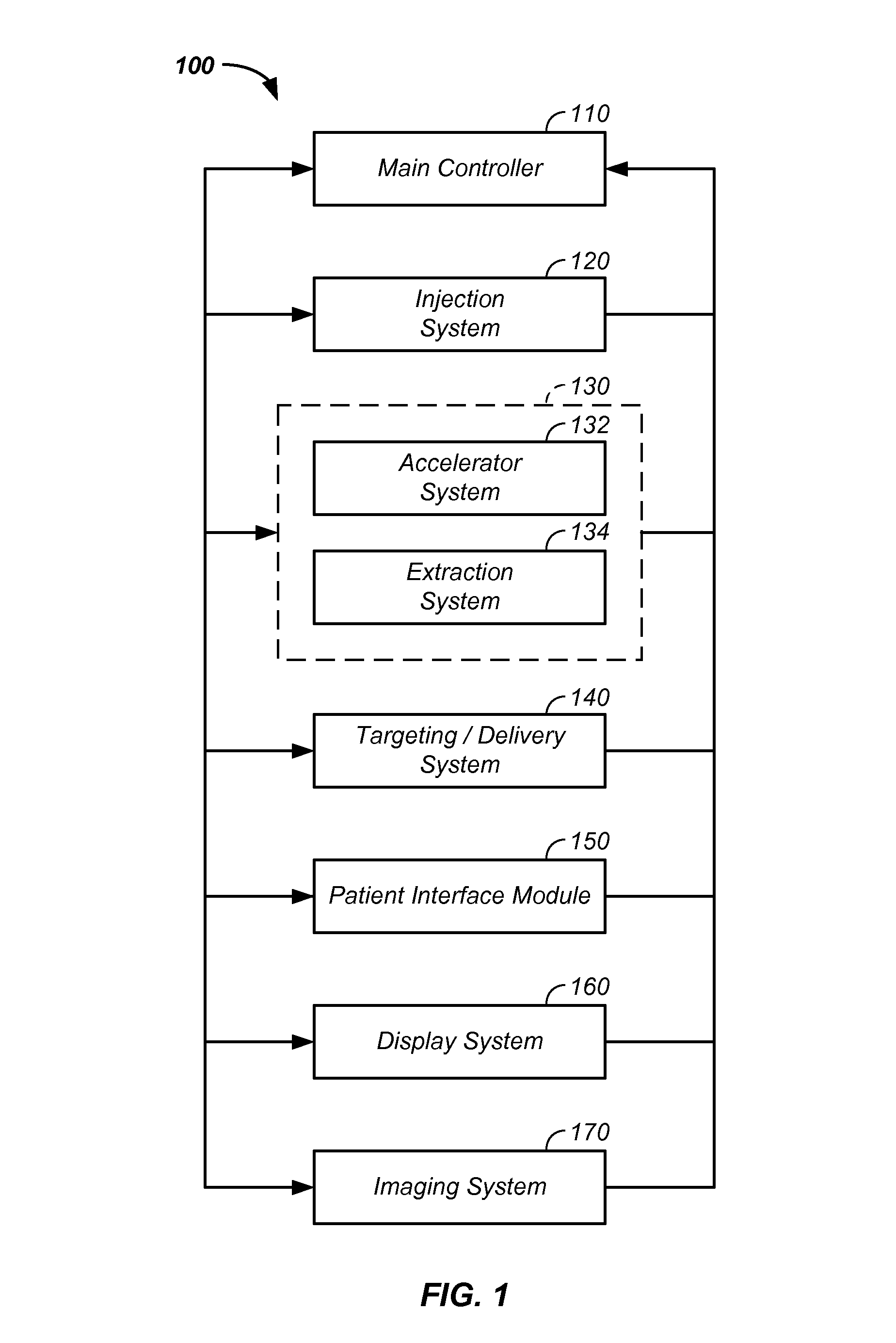
[0120]The invention comprises an X-ray system movable with an element of a charged particle cancer therapy system.

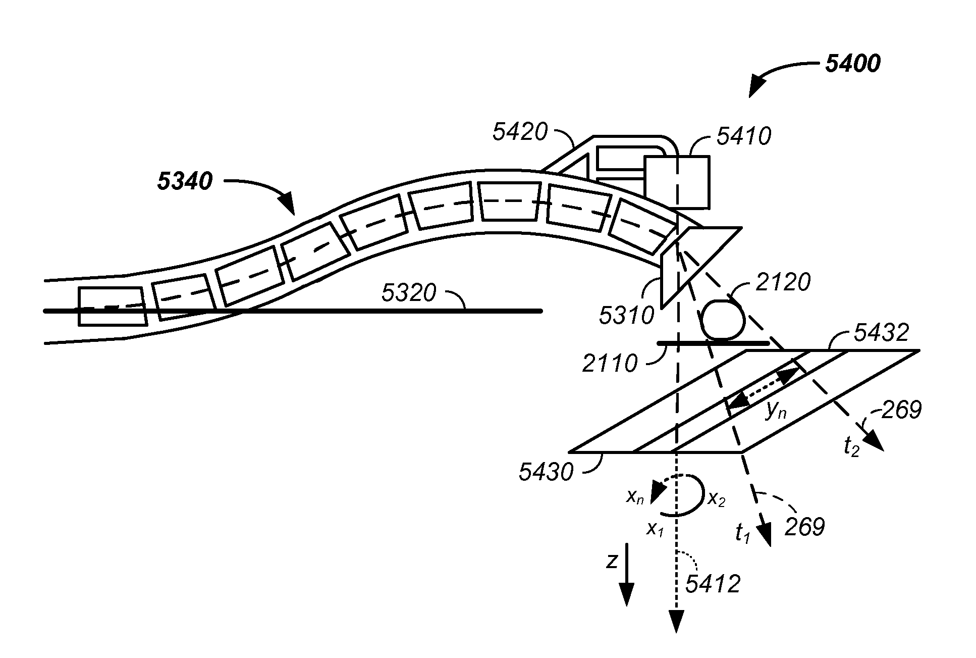
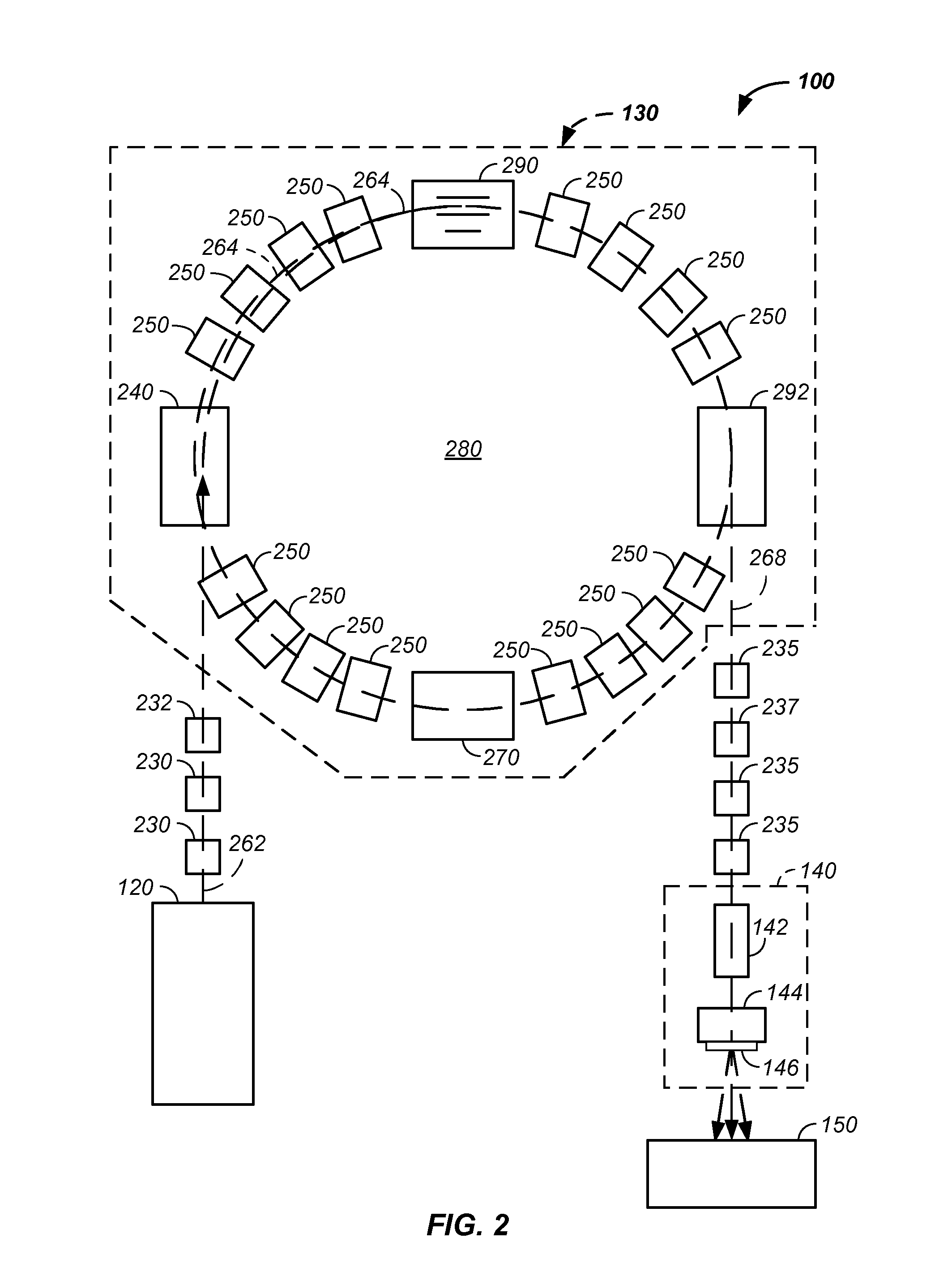
[0121]In one embodiment, an X-ray beamline, is co-moved, co-translated, and / or co-rotated with an element of a positively charged particle cancer treatment system. For example, an X-ray source or an element guiding an X-ray beam is rigidly mounted to and / or embedded into a moveable section of a charged particle beamline, such as a beamline arc between an accelerator and a patient that guides the positively charged particle beam to the tumor. As a gantry moves one or more elements of the beamline arc, the X-ray beam is also redirected to: (1) remain in a parallel and preferably an overlapped path with the charged particle beam, (2) to overlap a focal point of the positively charged particle beam path within the tumor, (3) to intersect the positively charged particle beam at a fixed distance from a longitudinal end of the beamline, such as a nozzle or final targeting magne...


PUM


Abstract

An imaging system apparatus and method of use thereof is described in combination with a co-movable charged particle beamline apparatus element, such as one or more elements held and dynamically positioned by a gantry, where the method and apparatus are optionally elements of a positively charged particle cancer therapy system. In one embodiment, an X-ray imaging element is rigidly and semi-permanently attached to and co-moved with a proton directing element. For example, as the gantry relocates one or more elements of a proton beamline arc, the X-ray beam is mechanically forced to co-relocate with the proton directing element and/or the final proton beam path.

Description

CROSS-REFERENCES TO RELATED APPLICATIONS[0001]This application is a continuation-in-part of U.S. patent application Ser. No. 14 / 216,788 filed Mar. 17, 2014, which[0002]is a continuation-in-part of U.S. patent application Ser. No. 13 / 572,542 filed Aug. 10, 2012, which is a continuation-in-part of U.S. patent application Ser. No. 12 / 425,683 filed Apr. 17, 2009, which claims the benefit of:[0003]U.S. provisional patent application No. 61 / 055,395 filed May 22, 2008, now U.S. Pat. No. 7,939,809 B2;[0004]U.S. provisional patent application No. 61 / 137,574 filed Aug. 1, 2008;[0005]U.S. provisional patent application No. 61 / 192,245 filed Sep. 17, 2008;[0006]U.S. provisional patent application No. 61 / 055,409 filed May 22, 2008;[0007]U.S. provisional patent application No. 61 / 203,308 filed Dec. 22, 2008;[0008]U.S. provisional patent application No. 61 / 188,407 filed Aug. 11, 2008;[0009]U.S. provisional patent application No. 61 / 188,406 filed Aug. 11, 2008;[0010]U.S. provisional patent applicati...

Claims


Application Information

Patent Timeline
IPC IPC(8): A61N5/10
CPCA61N5/1049A61N5/1067A61N2005/1061A61N2005/1087A61N5/1081G21K1/093G21K5/04H01J35/045H01J37/08H01J37/1475H05H13/04H05H2007/002H05H2007/048A61N5/107A61N5/1077A61N5/1082A61N2005/1097H05H9/00
Inventor BALAKIN, VLADIMIR
Owner BALAKIN ANDREY VLADIMIROVICH
Why Eureka
Try Eureka