High-efficiency compound regenerative electrical energy device

An electric energy device and composite regeneration technology, which is applied in the direction of regenerative fuel cells, circuits, fuel cells, etc., can solve the problems of complexing agent degradation, slow reaction rate, and high energy consumption, so as to achieve rapid regeneration, reduce energy consumption, and realize The effect of secondary use

Inactive Publication Date: 2016-09-21
JEREH TIANJIN PETROLEUM ENG & TECH
View PDF0 Cites 99 Cited by
  • Summary
  • Abstract
  • Description
  • Claims
  • Application Information

AI Technical Summary

Problems solved by technology

[0004] In order to solve the above technical problems, the present invention provides a high-efficiency composite regenerative power device to solve th

Method used


Image

  • High-efficiency compound regenerative electrical energy device

Examples


Embodiment

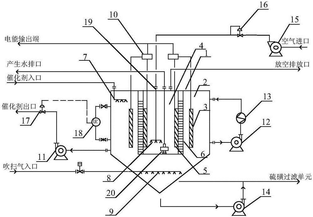
[0016] as attached figure 1 shown

[0017] The invention provides a high-efficiency composite regenerative electric energy device, comprising a reactor 1, an anode chamber 2, an anode plate 3, a cathode chamber 4, a cathode plate 5, a proton exchange membrane module 6, a liquid distributor 7, a gas distributor 8, and a purging Distributor 9, battery load 10, output pump 11, circulation pump 12, heater / cooler 13, slurry pump 14, blower 15, purge gas shut-off valve 16, flow regulating valve 17, magnetic flap level gauge 18, self-powered Type pressure regulating valve 19, submersible pump 20. The anode chamber 2 is arranged in the outer cylinder of the reactor 1; the anode plate 3 is arranged in the inside of the anode chamber 2; the cathode chamber 4 is arranged in the inner cylinder of the reactor 1; the cathode plate 5 is arranged On the inner wall of the cathode chamber 4; the proton exchange membrane module 6 is arranged between the anode chamber 2 and the cathode chamber ...


PUM


Abstract

The invention provides a high-efficiency compound regenerative electrical energy device. The device comprises a reactor, an anode chamber, an anode plate, a cathode chamber, a cathode plate, a proton exchange membrane module, a liquid distributor, a gas distributor, a purge distributor, a battery load, an output pump, a circulating pump, a heating/cooling device, a slurry pump, an air blower, a purge gas stop valve, a flow control valve, a magnetic flap liquidometer, a self-operated pressure-regulating valve, and an immersed pump. The gas distributor is disposed at the bottom of the cathode chamber, and the circulating pump is disposed in the middle of the reactor barrel. The air blower communicates with the gas distributor by the self-operated pressure-regulating valve, and the immersed pump is disposed at the bottom of the cathode chamber. The device uses the coupling mode of fuel cell and catalyst reactivation by means of the arrangement of air cathode fuel cell, is beneficial to improve the oxidation regeneration rate of the catalyst, and realizes the rapid regeneration of the complex catalyst.

Description

technical field [0001] The invention relates to the field of desulfurization and purification equipment, in particular to a high-efficiency composite regenerative electric energy device. Background technique [0002] As the society pays more and more attention to environmental protection, the effective control of the emission of sulfur-containing waste gas has become a part of the national environmental planning. H 2 S, further exhaust gas treatment is required to meet the emission standards. Contains H 2 The treatment of S acid gas usually adopts Clause sulfur recovery process (including various improved derivative processes) and liquid phase direct oxidation process. The Clause sulfur recovery process has strict requirements on the concentration of H2S in acid gas. The process is complex, with many equipment and supporting facilities, long investment recovery period and large area, especially for H 2 The working conditions with too low S concentration or large content ...

Claims


Application Information

Patent Timeline
IPC IPC(8): H01M8/18H01M8/0662
CPCH01M8/0675H01M8/188Y02E60/50
Inventor 江健于磊张庆锦
Owner JEREH TIANJIN PETROLEUM ENG & TECH
Why Eureka
Try Eureka