Check patentability & draft patents in minutes with Patsnap Eureka AI!

Drive control device for hybrid vehicle

a technology for hybrid vehicles and control devices, which is applied in the direction of hybrid vehicles, engine starters, machines/engines, etc., can solve the problems of generating a booming noise or deteriorating vibration of hybrid vehicles, and achieve the reduction the reduction of the effect of reducing the generation of noise and vibration

Inactive Publication Date: 2015-10-27
TOYOTA JIDOSHA KK
View PDF37 Cites 6 Cited by
  • Summary
  • Abstract
  • Description
  • Claims
  • Application Information

AI Technical Summary

Benefits of technology

The solution effectively reduces noise and vibration by selectively switching between drive modes based on the engine's operating point, ensuring the hybrid vehicle operates within regions that minimize these issues, thereby enhancing the vehicle's performance and comfort.

Problems solved by technology

According to the conventional arrangement of the hybrid vehicle described above, however, there is a risk of generation of a booming noise or deterioration of vibrations of the hybrid vehicle, when frequency of a rotary motion pulsation of the engine is coincident with the resonance frequency of a power transmitting system in the hybrid vehicle while an operating point of the engine lies in a predetermined range.

Method used


Image

  • Drive control device for hybrid vehicle
  • Drive control device for hybrid vehicle
  • Drive control device for hybrid vehicle

Examples


first embodiment

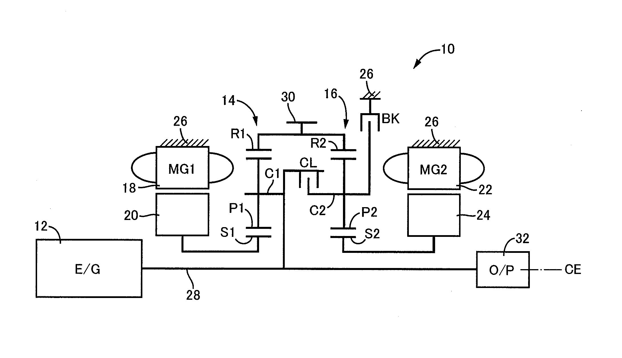
[0035]FIG. 1 is the schematic view for explaining an arrangement of a hybrid vehicle drive system 10 (hereinafter referred to simply as a “drive system 10”) to which the present invention is suitably applicable. As shown in FIG. 1, the drive system 10 according to the present embodiment is of a transversely installed type suitably used for an FF (front-engine front-drive) type vehicle, and is provided with a main vehicle drive power source in the form of an engine 12, a first electric motor MG1, a second electric motor MG2, a first differential mechanism in the form of a first planetary gear set 14, and a second differential mechanism in the form of a second planetary gear set 16, which are disposed on a common center axis CE. The drive system 10 is constructed substantially symmetrically with respect to the center axis CE. In FIG. 1, a lower half of the drive system 10 is not shown. This description applies to other embodiments which will be described.

[0036]The engine 12 is an inte...

second embodiment

[0082]FIG. 14 is the schematic view for explaining an arrangement of a hybrid vehicle drive system 100 (hereinafter referred to simply as a “drive system 100”) according to another preferred embodiment of this invention. In this drive system 100 shown in FIG. 14, the second planetary gear set 16, clutch CL and brake BK are disposed on one side of the first planetary gear set 14 remote from the engine 12, such that the second electric motor MG2 is interposed between the first planetary gear set 14, and the second planetary gear set 16, clutch CL and brake BK, in the axial direction of the center axis CE. Preferably, the clutch CL and brake BK are disposed at substantially the same position in the axial direction of the center axis CE. That is, the drive system 100 is configured such that the first electric motor MG1, first planetary gear set 14, second electric motor MG2, second planetary gear set 16, clutch CL, and brake BK are disposed coaxially with each other, in the order of des...

third embodiment

[0083]FIG. 15 is a schematic view for explaining an arrangement of a hybrid vehicle drive system 110 (hereinafter referred to simply as a “drive system 110”) according to a further preferred embodiment of this invention. In this drive system 110 shown in FIG. 15, the first planetary gear set 14, clutch CL, second planetary gear set 16 and brake BK which constitute a mechanical system are disposed on the side of the engine 12, while the first electric motor MG1 and second electric motor MG2 which constitute an electric system are disposed on one side of the mechanical system remote from the engine 12. That is, the drive system 110 is configured such that the first planetary gear set 14, clutch CL, second planetary gear set 16, brake BK, second electric motor MG2, and first electric motor MG1 are disposed coaxially with each other, in the order of description from the side of the engine 12, in the axial direction of the center axis CE. The hybrid vehicle drive control device according...


PUM


Abstract

A drive control device for a hybrid vehicle which is provided with: a first differential mechanism and a second differential mechanism which have a total of five rotary elements; and an engine, a first electric motor, a second electric motor and an output rotary member which are respectively connected to four rotary elements of said five rotary elements, and which has at least a first drive mode and a second drive mode in which the engine is operated and which are established by selectively connecting a rotary element of said five rotary elements which is connected to said engine, and a rotary element of said five rotary elements which is not connected to any of said engine, said first electric motor, said second electric motor and said output rotary member, to each other through a clutch, or selectively fixing the rotary element connected to said engine and the rotary element not connected to any of said engine, said first electric motor, said second electric motor and said output rotary member, to a stationary member through a brake, the drive control device comprising: a drive mode control portion configured to place the hybrid vehicle selectively in the first drive mode in which said engine is operated, in an engaged state of said brake and in a released state of said clutch, and the second drive mode in which said engine is operated, in a released state of said brake and in an engaged state of said clutch, said drive control portion inhibiting the hybrid vehicle from being placed in said second drive mode when an operating point of said engine lies in a predetermined region, and permitting the hybrid vehicle to be placed in said first drive mode when the operating point of the engine lies in said predetermined region.

Description

CROSS REFERENCE TO RELATED APPLICATIONS[0001]This application is a National Stage of International Application No. PCT / JP2011 / 079422, filed Dec. 19, 2011, the contents of all of which are incorporated herein by reference in their entirety.TECHNICAL FIELD[0002]The present invention relates to an improvement of a drive control device for a hybrid vehicle.BACKGROUND ART[0003]There is known a hybrid vehicle which has at least one electric motor in addition to an engine such as an internal combustion engine, which functions as a vehicle drive power source. Patent Document 1 discloses an example of such a hybrid vehicle, which is provided with an internal combustion engine, a first electric motor and a second electric motor. This hybrid vehicle is further provided with a brake which is configured to fix an output shaft of the above-described internal combustion engine to a stationary member, and an operating state of which is controlled according to a running condition of the hybrid vehic...

Claims


Application Information

Patent Timeline
Patent Type & Authority Patents(United States)
IPC IPC(8): B60L9/00B60K6/445B60K6/365B60W10/12F02D29/02B60W10/06B60K6/387B60W20/00B60K6/38F02N11/08
CPCB60W10/12B60K6/365B60K6/387B60K6/445B60W10/06B60W20/1084B60W20/20F02D29/02B60K2006/381F02N11/0814Y02T10/6239Y10S903/93B60W20/17Y02T10/62
Inventor HAYASHI, KOJITERASHIMA, MASATOHARADA, HIROYASUONO, TOMOHITOISHII, HIROYUKI
Owner TOYOTA JIDOSHA KK
Features
  • R&D
  • Intellectual Property
  • Life Sciences
  • Materials
  • Tech Scout
  • Unparalleled Data Quality
  • Higher Quality Content
  • 60% Fewer Hallucinations
Learn More