Exhaust system with mixing and/or evaporating device

a technology of evaporation device and exhaust system, which is applied in the direction of exhaust treatment, mixer, mixing method, etc., can solve the problems of droplets hitting the wall, difficult to return the reducing agent from such a film on the wall, and difficult to complete evaporation and mixing of the reducing agent before entering the scr catalytic converter. , to achieve the effect of simple and simpl

Active Publication Date: 2015-10-27
EBERSPACHER EXHAUST TECH GMBH & CO KG
View PDF10 Cites 5 Cited by
  • Summary
  • Abstract
  • Description
  • Claims
  • Application Information

AI Technical Summary

Benefits of technology

[0008]An object of the present invention is to provide an improved or at least different embodiment for a mixing and / or evaporating device of the above-mentioned type or for an exhaust system equipped therewith, which embodiment is characterized by a simpler and therefore more inexpensive design. In addition, improved mixing of the educt with the exhaust gas as well as preventing of the formation of a film on the wall shall, furthermore, be achieved.
[0017]The course of the flow at a site located father downstream at the inner wall of the mixing chamber can be influenced by displacing the discharge-side axial end of the first long side wall in the direction of flow. As a result, mixing of the reducing agent with the exhaust gas stream can be achieved again at the inner wall in the vicinity of the SCR catalytic converter.
[0019]In case of a stepped design of the mixing and / or evaporating device on the incoming flow side as described above, this mixing and / or evaporating device can be arranged, as described, partly in front of the discharge opening of the oxidation catalytic converter without narrowing the flow cross section on the discharge side of the oxidation catalytic converter. In case of guide blades arranged on the incoming flow side, this means that a row of guide blades can be arranged closer to the means for introducing the reducing agent without reducing the flow cross section at the discharge-side end of the oxidation catalytic converter. The formation of a film on the wall can thus be prevented and very early size reduction of the droplets of reducing agent into finer droplets can take place. On the whole, the row of guide blades arranged farthest upstream is thus arranged closer to the nozzle of the reducing agent feed means, as a result of which the reducing agent droplets reach the guide blades of the mixing and / or evaporating device before they can reach the wall. In particular, the reducing agent is divided by the guide blades into finer droplets, which can thus follow the course of the flow more easily and can be evaporated better than coarser droplets.
[0026]The distance in axial direction from the guide blades at an axial end of the first long side wall to the opposite axial end of the first long side wall is greater in another advantageous embodiment in case of guide blades that are arranged closer to the first short side wall than in case of guide blades that are arranged closer to the second short side wall, and the distance in axial direction from the guide blades at an axial end of the second long side wall to the opposite axial end of the second long side wall is shorter in case of guide blades that are arranged loser to the first short side wall than in case of guide blades that are arranged loser to the second short side wall.
[0027]Due to this arrangement, the row of guide blades of the first long side wall extends from the first short side wall linearly or concavely along a radius obliquely in the direction of flow and the row of guide blades of the second long side wall extends from the first short side wall linearly or concavely along a radius obliquely against the direction of flow. Taking the flow conditions in the mixing chamber and the manner in which the reducing agent is introduced into account, the distance of the individual guide blades can be selected as a result to be such that the smallest possible quantity of reducing agent will reach the wall of the mixing chamber and very good mixing of the reducing agent will take place.
[0029]The flat cross section of the mixing and / or evaporating device makes it possible to arrange the guide blades at a right angle to the axial direction in a row next to each other, as a result of which a large-area lateral deflection of the flow in the direction of one of the short side walls is possible. The introduction of the reducing agent into the exhaust gas stream takes place after the flow is discharged from the oxidation catalytic converter, i.e., in an area in which the flow is deflected in the mixing chamber by 90°. Deflection in a direction that is at a right angle thereto, i.e., in the direction of the short side walls, thus make possible a highly effective mixing of the reducing agent with the exhaust gas stream, because deflection of the flow takes place in two directions that are at a right angle to one another.

Problems solved by technology

However, only the relatively short mixing chamber between the oxidation catalytic converter and the SCR catalytic converter is available for the evaporation and mixing of the reducing agent in the above-described embodiment of the exhaust system, which makes complete evaporation and mixing of the reducing agent before entry into the SCR catalytic converter difficult.
Since the mixing chamber may have a relatively flat flow cross section, this may cause droplets to hit the wall of the mixing chamber and form a film on the wall before the reducing agent is evaporated.
It is very difficult to return the reducing agent from such a film on the wall into the exhaust gas stream and to evaporate and mix it.

Method used


Image

  • Exhaust system with mixing and/or evaporating device
  • Exhaust system with mixing and/or evaporating device
  • Exhaust system with mixing and/or evaporating device

Examples


Embodiment Construction

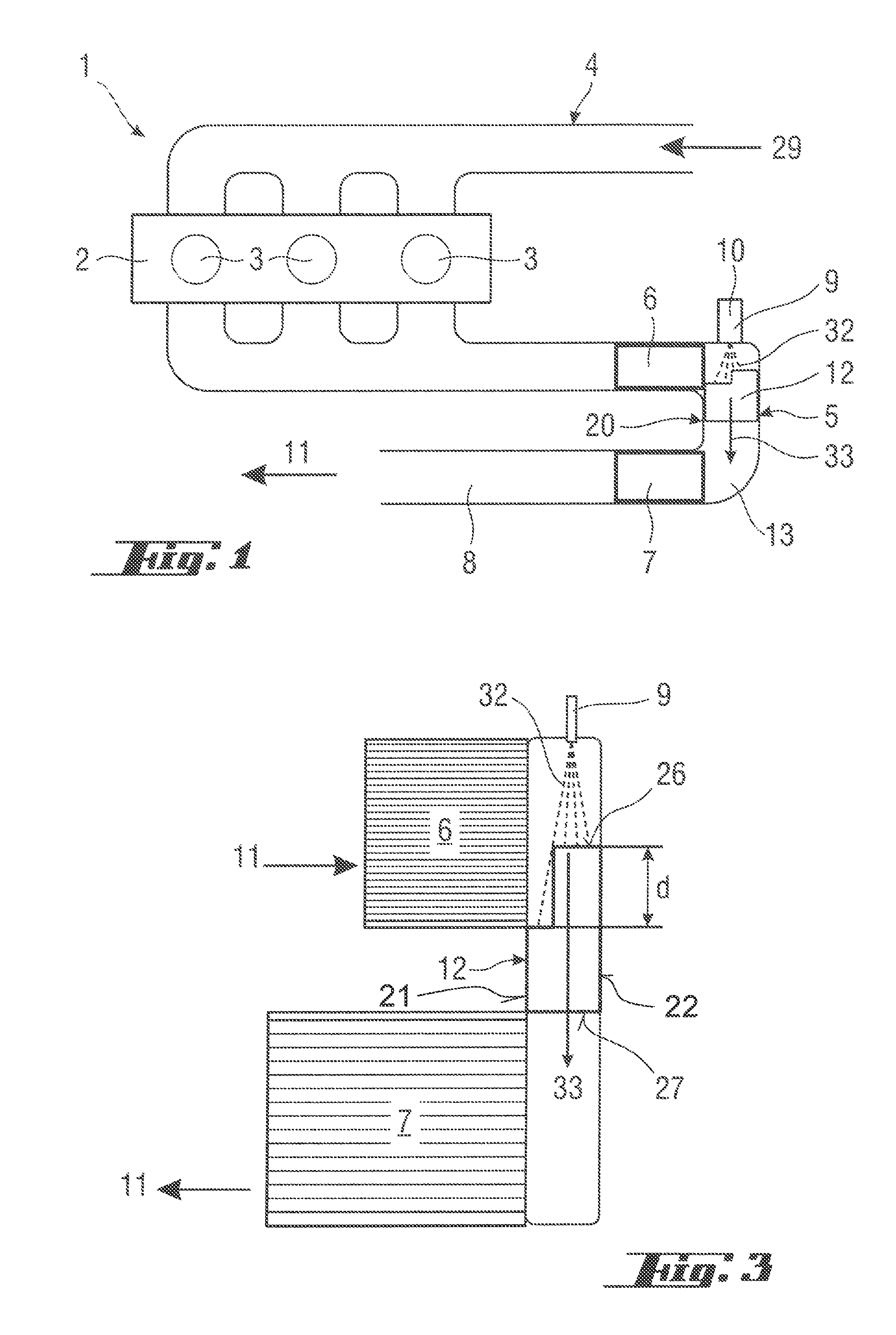
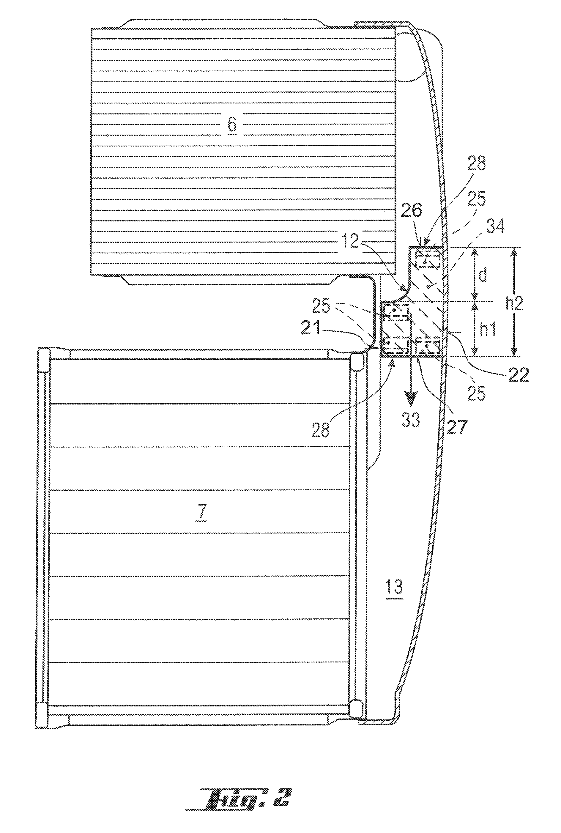
[0045]Referring to the drawings in particular, corresponding to FIG. 1, an internal combustion engine 1 comprises in the usual manner an engine block 2, which has a plurality of cylinders 3. A fresh air feed unit 4 supplies the cylinders 3 of the engine block 2 with fresh air.

[0046]A corresponding fresh air stream is indicated by an arrow 29. An exhaust system 5 removes combustion exhaust gases from the cylinders 3 of the engine block 2 during the operation of the internal combustion engine 1. Furthermore, the exhaust system 5 brings about exhaust gas cleaning and exhaust gas treatment.

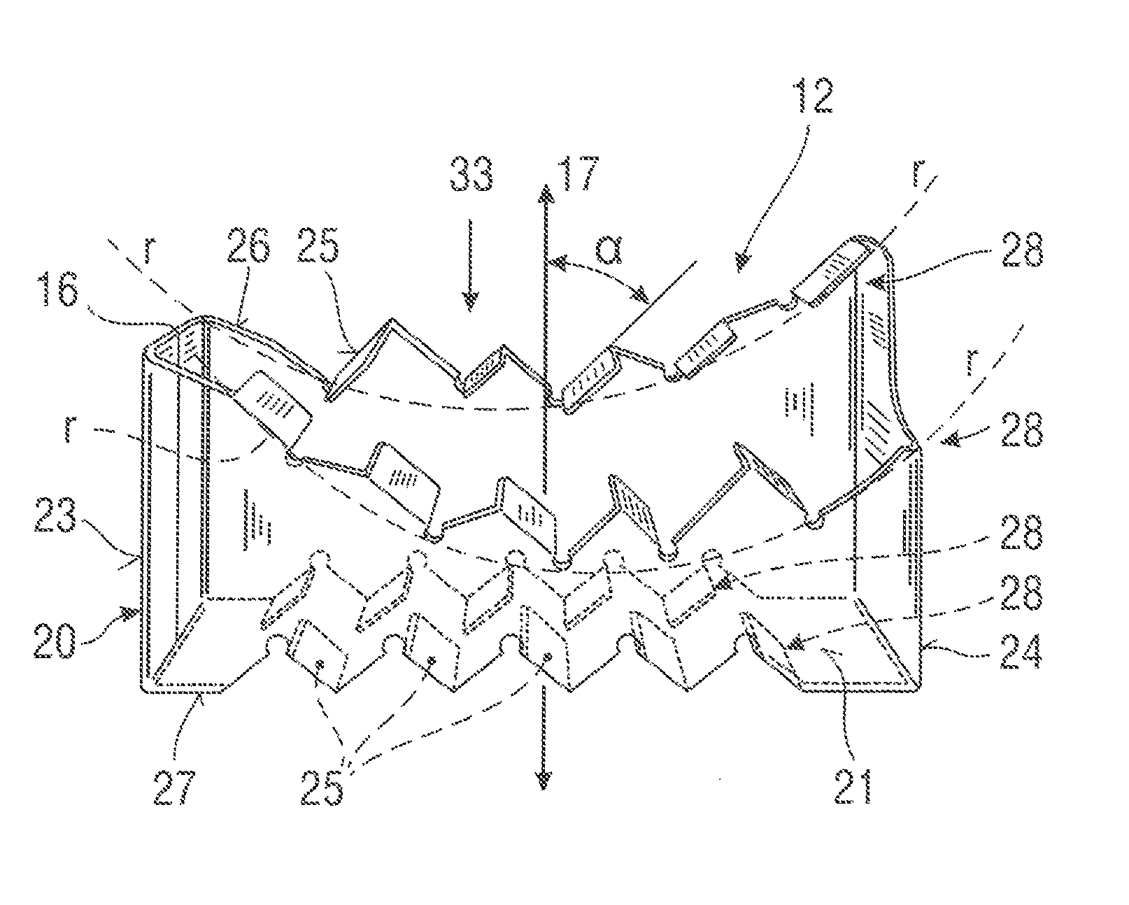
[0047]The exhaust system 5 is equipped for this with at least one diesel oxidation catalytic converter 6 and with an SCR catalytic converter 7, which are integrated into an exhaust gas line 8 of the exhaust system 5. To make a space-saving embodiment possible, a U-shaped arrangement of diesel oxidation catalytic converter 6 and SCR catalytic converter 7 may be provided. The diesel oxidation catalytic ...


PUM

PropertyMeasurementUnit
pitch angleaaaaaaaaaa
lengthaaaaaaaaaa
distanceaaaaaaaaaa

Abstract

A mixer / evaporator or an exhaust system (5) of an internal combustion engine (1), includes a carrier (20) surrounding, in a circumferential direction, a flat cross section of a mixing / evaporating device (12), through which exhaust gases flow and which extends at a right angle to the axial direction (17). The carrier has opposite side walls, wherein short side walls (23, 24) connect each long side walls (21, 22) to one another. Guide blades (25) project in a direction of the respective opposite long side wall, are set at an angle in relation to the axial direction and are arranged at one of the long side walls at least one axial end (26, 27). An axial end of the first long side walls is offset in the axial direction in relation to the axial end of the second long side wall on the same side of the mixing / evaporating device.

Description

CROSS REFERENCE TO RELATED APPLICATIONS[0001]This application claims the benefit of priority under 35 U.S.C. §119 of Grerman Patent Application DE 10 2012 016 423.8 filed Aug. 21, 2012, the entire contents of which are incorporated herein by reference.FIELD OF THE INVENTION[0002]The present invention pertains to a mixing and / or evaporating device for an exhaust system of an internal combustion engine, especially of a motor vehicle. The present invention pertains, in addition, to an exhaust system equipped with such a mixer / evaporator.BACKGROUND OF THE INVENTION[0003]An exhaust system of an internal combustion engine is usually equipped with means for cleaning and treating the exhaust gases removed from the internal combustion engine. It may be necessary in this connection to introduce a liquid educt into the exhaust gas stream, to evaporate it in same and to mix it with the exhaust gas. It may be necessary, for example, to add a fuel to the exhaust gas upstream of an oxidation catal...

Claims


Application Information

Patent Timeline
Patent Type & Authority Patents(United States)
IPC IPC(8): F01N1/00F01N3/28B01F3/04B01F5/06B01F5/04F01N3/10F01N3/18F01N3/20F01N13/00
CPCF01N3/18B01F3/04049B01F5/0473B01F5/0616F01N3/106F01N3/2892B01F2005/0639F01N3/2066F01N13/009F01N2240/20F01N2610/02Y02A50/20B01F23/2132B01F25/3141B01F25/4315B01F25/431974B01F25/43151
Inventor CALVO, SILVIA
Owner EBERSPACHER EXHAUST TECH GMBH & CO KG
Why Eureka
Try Eureka