3D inspection using cameras and projectors with multiple-line patterns

a technology of multiple-line pattern and projector, applied in the field of optical inspection systems, can solve the problems of increasing the cost and complicating the system mechanism, and achieve the effect of simple displacement and simple solution

Active Publication Date: 2015-10-27
VIT SA
View PDF46 Cites 3 Cited by
  • Summary
  • Abstract
  • Description
  • Claims
  • Application Information

AI Technical Summary

Benefits of technology

[0012]An object of an embodiment of the present invention is to provide an installation of inspection by image analysis which overcomes all or part of the disadvantages of known methods and installations.
[0013]According to a first aspect, an object of an embodiment of the present invention is to provide a solution which is particularly well adapted to an in-line processing and which simplifies displacements.
[0014]According to this first aspect, another object of another embodiment of the present invention is to provide a particularly simple solution for a two-dimensional analysis.

Problems solved by technology

This complicates the system mechanism and increases its cost due to the accuracy required for the drive motors.

Method used


Image

  • 3D inspection using cameras and projectors with multiple-line patterns
  • 3D inspection using cameras and projectors with multiple-line patterns
  • 3D inspection using cameras and projectors with multiple-line patterns

Examples


Embodiment Construction

[0038]The same elements have been designated with the same reference numerals in the different drawings, which have been drawn out of scale. For clarity, only those steps and elements which are useful to the understanding of the present invention have been shown and will be described. In particular, the image processing algorithms used by the present invention are known per se and will not be detailed. Further, the practical implementation of a digital image sensor has not been detailed, the present invention being compatible with any usual black and white or color array camera, for example, charge-coupled devices (CCD) or CMOS sensors.

[0039]The present invention will first be described in relation with its first aspect, applied to an embodiment for a two-dimensional photography installation.

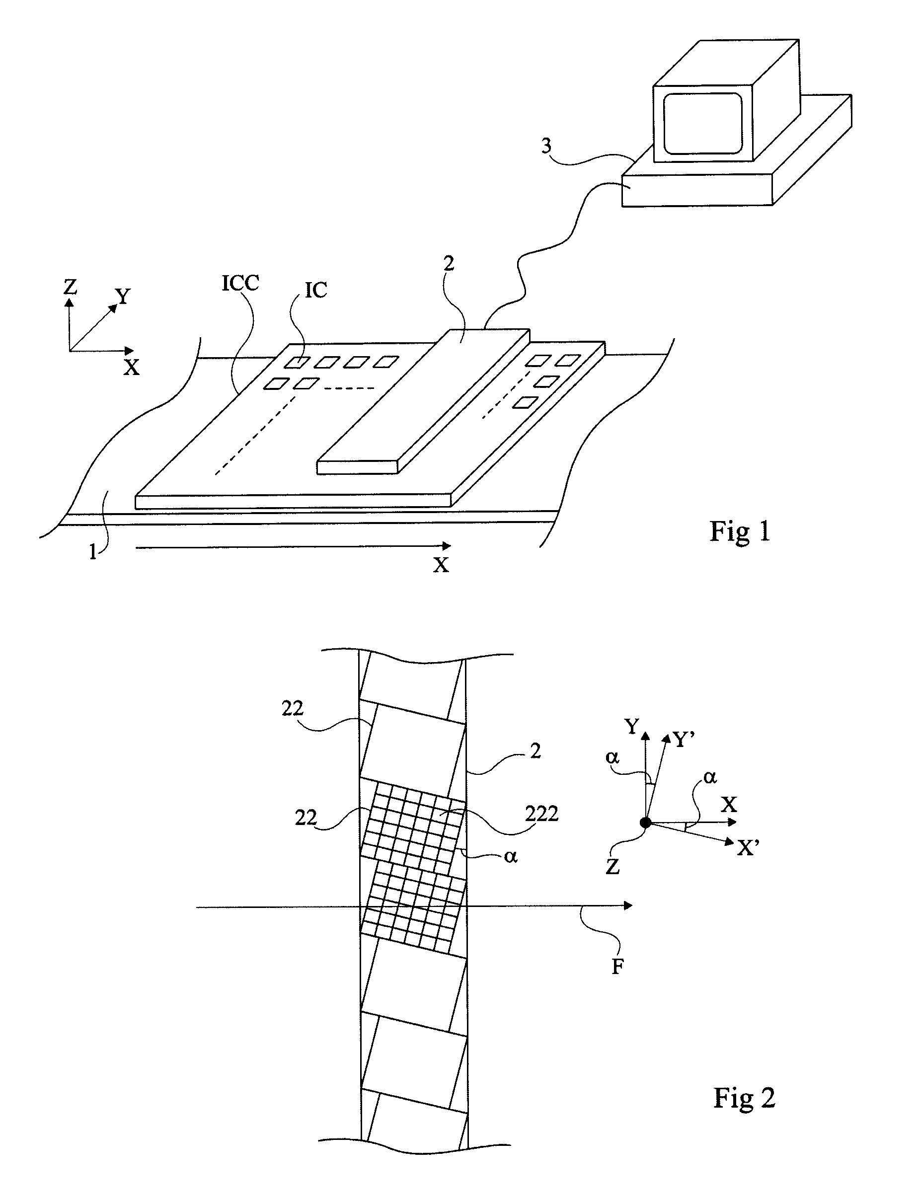
[0040]FIG. 2 is a simplified top view showing a set 2 of image sensors 22 of an analysis installation according to an embodiment of the first aspect of the present invention. It is provided to d...


PUM

PropertyMeasurementUnit
angleaaaaaaaaaa
angleaaaaaaaaaa
angleaaaaaaaaaa

Abstract

An installation of optical inspection of integrated circuits or the like includes a photographic system placed above a scene in a plane defined by a first and a second direction, the photographic system having several digital cameras each having an orthogonal array of pixels, all cameras having their respective optical axes inclined by a first angle with respect to a third direction perpendicular to the two others; and two projectors of determined patterns, these patterns being such that two straight lines projected by each of the projectors are aligned in the plane defined by the first two directions and are coplanar with a straight line interconnecting the optical centers of the two projectors.

Description

CROSS REFERENCE TO RELATED APPLICATIONS[0001]The instant disclosure is related to a co-pending application filed under Ser. No. 13 / 190,149 on Jul. 25, 2011.BACKGROUND OF THE INVENTION[0002]1. Field of the Invention[0003]The present invention generally relates to optical inspection systems and, more specifically, to systems for the in-line analysis of electronic circuits. The present invention more specifically relates to systems equipped with digital cameras.[0004]2. Discussion of Prior Art[0005]FIG. 1 schematically shows an installation of the type to which the present invention applies as an example. Electronic circuits IC, for example supported by a printed circuit board ICC, are placed, for example, on a conveyor of an in-line optical inspection installation. Such an installation comprises a system 2 of digital cameras, connected to an image processing computer system 3. Conveyor 1 is capable of moving in a plane X, Y (generally horizontal) and, for a series of photographs, in o...

Claims


Application Information

Patent Timeline
Patent Type & Authority Patents(United States)
IPC IPC(8): H04N7/18G06T1/00G01N21/88G01B11/25G01N21/956G01R31/308
CPCG01N21/8851G01B11/2545G01N21/956G06T1/0007G01N2201/0635G01R31/308H05K3/00
Inventor PERRIOLLAT, MATHIEU
Owner VIT SA
Why Eureka
Try Eureka