
Bulldozer

a bulldozer and cylinder head technology, applied in the field of bulldozers, can solve the problems of reduced workability, restricted areas of the side portions of the blades of the working implement visible to the operator, and large horizontal width of the engine compartment, so as to prevent deterioration of workability

Active Publication Date: 2015-11-03
KOMATSU LTD
View PDF21 Cites 9 Cited by
  • Summary
  • Abstract
  • Description
  • Claims
  • Application Information

AI Technical Summary

Benefits of technology

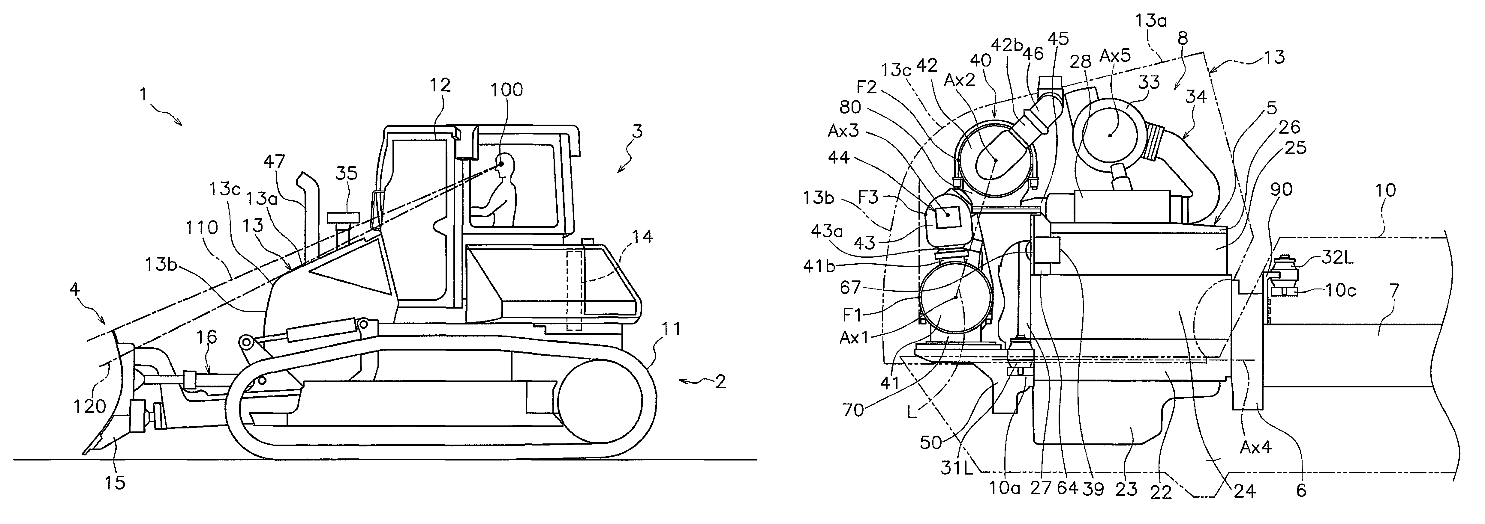
The patent describes a bulldozer with two exhaust treatment devices that are placed in the engine compartment. To prevent the affect on the operator's workability, the invention provides a design that allows for the exhaust treatment devices to be placed in front of the engine, with the first device positioned higher and the front edge more forward than the second device. This design ensures that the upper surface of the engine cover does not need to be raised, which could restrict the operator's visibility and affect workability. Overall, this design prevents the invention from reducing the workability of the bulldozer.

Problems solved by technology

When the upper surface of the engine cover is raised, then the region visible to the operator on the upper portion of the blade of the working implement becomes restricted, so that the workability is reduced.
Moreover, when these two or more exhaust treatment devices are disposed at the side of the engine, then the horizontal width of the engine compartment becomes large, and the regions visible to the operator at the side portions of the blade of the working implement become restricted.

Method used


Image

  • Bulldozer
  • Bulldozer
  • Bulldozer

Examples


Embodiment Construction

[0032]Overall Structure

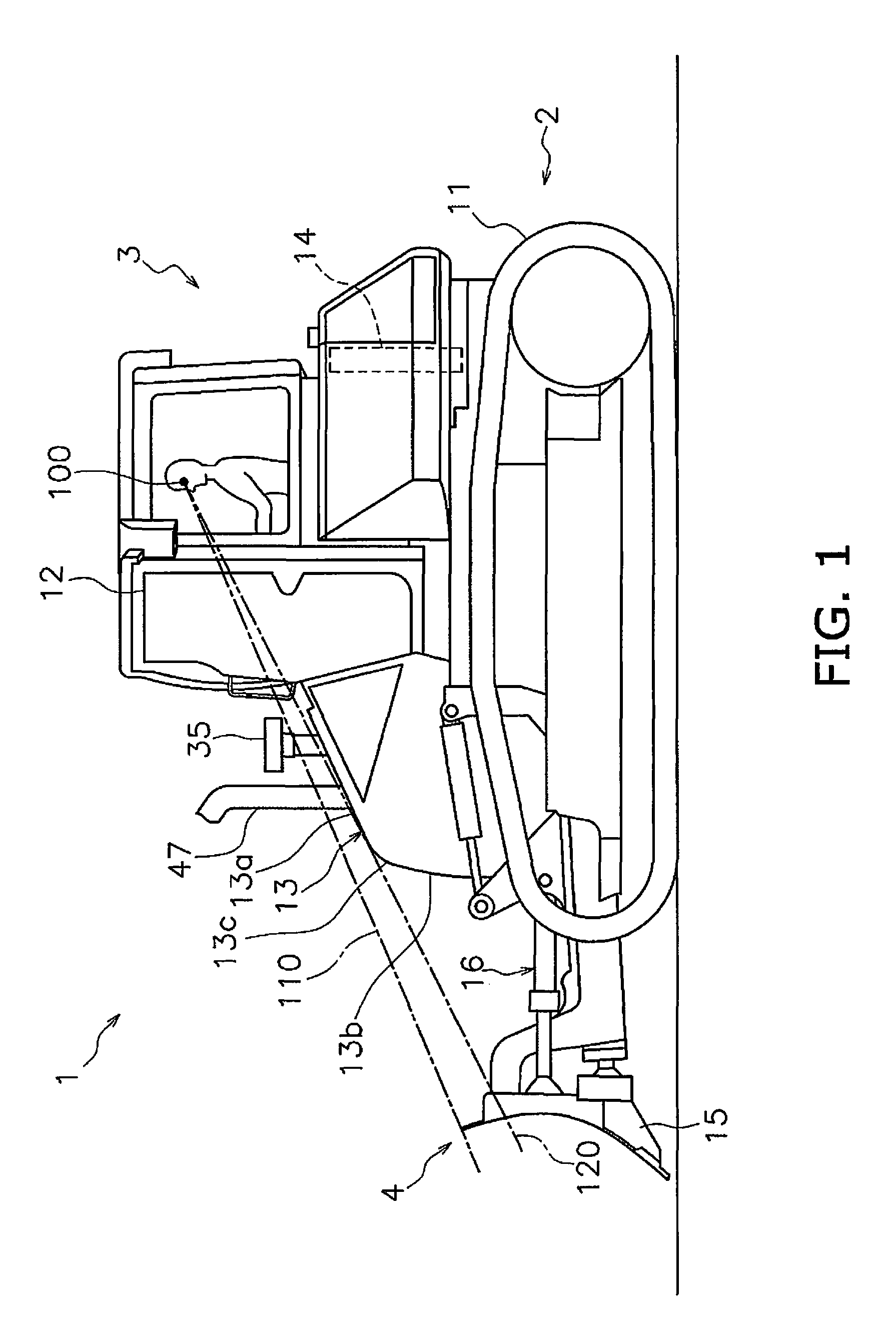
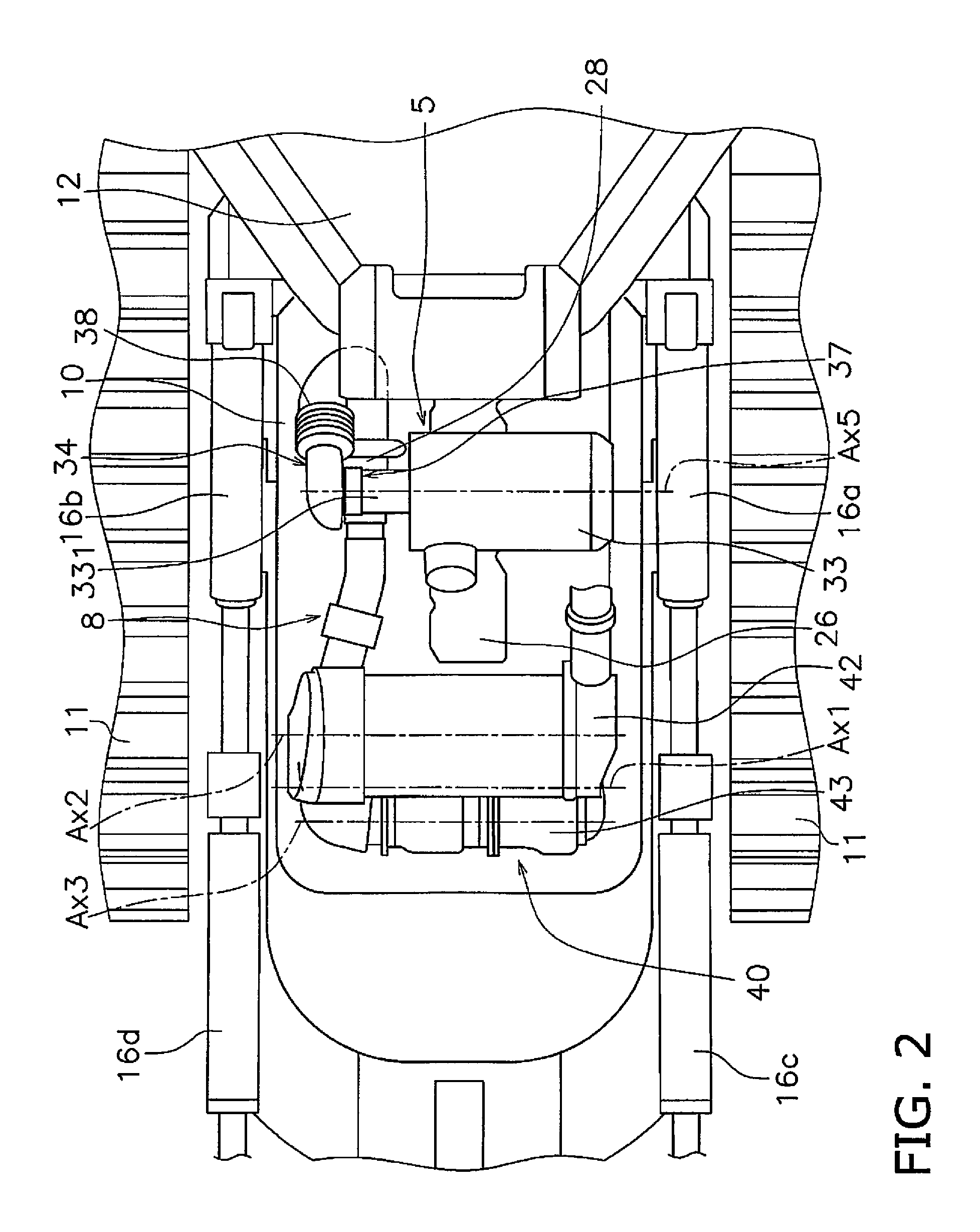
[0033]A left side view of a bulldozer 1 according to an exemplary embodiment of the present invention is shown in FIG. 1. A top view illustrating a part of the bulldozer according to the exemplary embodiment of the present invention is shown in FIG. 2. In FIG. 2, an engine compartment 8 is shown in a state in which an engine cover 13, which will be described hereinafter, has been removed. It should be understood that, in the following explanation, the “front / rear direction” means the front / rear direction of the bulldozer 1. To put it in other words, the front / rear direction means the front / rear direction as seen by an operator sitting in a cab (an operator compartment) 12. Moreover, the left / right direction means the left / right direction as seen by an operator sitting in the cab (the operator compartment). Furthermore, the lateral direction means the direction lateral to the vehicle, i.e. to the bulldozer 1, such that it means either one of the left direction ...


PUM


Abstract

A bulldozer includes a blade, an engine, a first exhaust treatment device, a second exhaust treatment device, a relay connection pipe, and an engine cover. The first exhaust treatment device is disposed in front of the engine and lower than the upper surface thereof. The second exhaust treatment device is disposed above the first exhaust treatment device. The relay connection pipe is disposed above the first exhaust treatment device and below the second exhaust treatment device. The longitudinal directions of the first and second exhaust treatment devices extend along the vehicle lateral direction. As seen from the top of the vehicle, the second exhaust treatment device overlaps at least a part of the first exhaust treatment device. As seen from the side of the vehicle, the front edge of the first exhaust treatment device is positioned forward of the front edge of the second exhaust treatment device.

Description

CROSS-REFERENCE TO RELATED APPLICATIONS[0001]This application is a U.S. National stage application of International Application No. PCT / JP2013 / 062477, filed on Apr. 26, 2013.BACKGROUND[0002]1. Field of the Invention[0003]The present invention relates to a bulldozer, which is one type of work vehicle.[0004]2. Background Information[0005]In Japanese Laid-Open Patent Publication 2005-113674, a bulldozer is disclosed in which the upper surface of the engine cover is tilted forward and also downward (refer to Japanese Laid-Open Patent Publication 2005-113674). With the bulldozer the workability is enhanced, because the operator is able visually to check the upper portion of the blade, i.e. of the working implement.[0006]From the standpoint of protection of the natural environment, a work vehicle, such as a bulldozer, needs purifying of the exhaust (refer to Publication of U.S. Pat. No. 8,141,535B2). Therefore, it is nowadays practiced to mount an exhaust treatment device to a work vehicl...

Claims


Application Information

Patent Timeline
Patent Type & Authority Patents(United States)
IPC IPC(8): B60K13/04E02F9/08F01N13/00F01N13/18
CPCE02F9/0866F01N13/009F01N13/1805F01N2340/04F01N2590/08E02F3/7631B60K13/04B60Y2200/411
Inventor SAKAI, KIYOTAKA
Owner KOMATSU LTD
Learn More