Imaging lens
a technology of imaging lens and spherical lens, which is applied in the field of imaging lens, can solve the problems of poor wide-angle and inadequate lens brightness
- Summary
- Abstract
- Description
- Claims
- Application Information
AI Technical Summary
Benefits of technology
Problems solved by technology
Method used
Image


Examples
embodiment 1
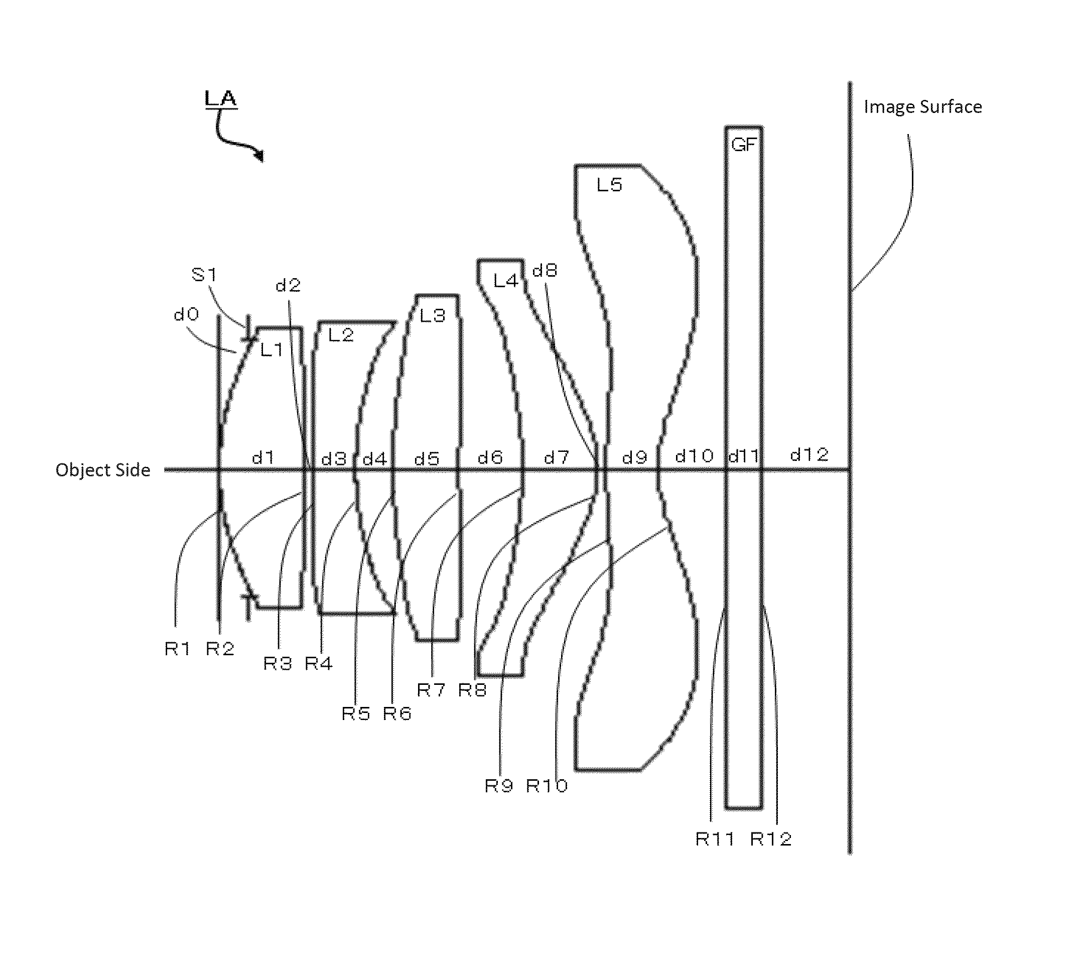
[0127]FIG. 2 shows an image lens LA in accordance with Embodiment 1 of the present invention.
[0128]
TABLE 1RdndνdS1∞d0 =−0.150R11.79881d1 =0.555nd11.5441ν156.12R2−15.35058d2 =0.090R312.70895d3 =0.360nd21.6355ν223.97R42.19119d4 =0.260R57.82508d5 =0.530nd31.5441ν356.12R6−9.46622d6 =0.340R7−2.28449d7 =0.560nd41.5441ν456.12R8−0.75014d8 =0.050R95.74482d9 =0.485nd51.5441ν556.12R100.74883d10 =0.500R11∞d11 =0.300nd61.5441ν656.12R12∞d12 =0.495
[0129]
TABLE 2RdndνdS1∞d0 =−0.120R11.54221d1 =0.640nd11.5441ν156.12R2−12.75467d2 =0.050R312.90064d3 =0.260nd21.6355ν223.97R42.22425d4 =0.340R533.00891d5 =0.370nd31.5441ν356.12R6−11.00300d6 =0.485R7−2.15212d7 =0.590nd41.5441ν456.12R8−0.79044d8 =0.055R95.76220d9 =0.410nd51.5441ν556.12R100.75500d10 =0.500R11∞d11 =0.300nd61.5441ν656.12R12∞d12 =0.500
[0130]Referring to Tables 1-2, together with Table 11, we will see that the image lens LA satisfies conditions (1)˜(10). The spherical aberration (axial chromatic aberration) of the image lens LA of embodiment 1 is...
embodiment 2
[0131]FIG. 6 shows an image lens LA in accordance with Embodiment 2 of the present invention.
[0132]
TABLE 3RdndνdS1∞d0 =−0.120R11.54221d1 =0.640nd11.5441ν156.12R2−12.75467d2 =0.050R312.90064d3 =0.260nd21.6355ν223.97R42.22425d4 =0.340R533.00891d5 =0.370nd31.5441ν356.12R6−11.00300d6 =0.485R7−2.15212d7 =0.590nd41.5441ν456.12R8−0.79044d8 =0.055R95.76220d9 =0.410nd51.5441ν556.12R100.75500d10 =0.500R11∞d11 =0.300nd61.5441ν656.12R12∞d12 =0.500
[0133]
TABLE 4kA4A6A8A10A12A14A16R1−8.6759E−011.2023E−02−4.6045E−03−3.3458E−024.1005E−028.8762E−03−1.5201E−011.0250E−01R2−4.5447E+02−4.1819E−02−6.7246E−023.7634E−02−5.9607E−024.9968E−024.6079E−02−4.1423E−02R31.1943E+02−2.4686E−02−8.4559E−021.1848E−01−6.3233E−027.6654E−021.2097E−02−3.1586E−02R42.7057E−01−6.9241E−033.1396E−026.3328E−02−7.7813E−027.9283E−022.8929E−03−1.3551E−02R5−4.1160E+02−1.2914E−02−1.0187E−021.8485E−020.0000E+000.0000E+000.0000E+000.0000E+00R6−7.2716E+01−1.1487E−021.1134E−023.7420E−030.0000E+000.0000E+000.0000E+000.0000E+00R71.1474E+007...
embodiment 3
[0135]FIG. 10 shows an image lens LA in accordance with Embodiment 3 of the present invention.
[0136]
TABLE 5RdndνdS1∞d0 =−0.150R11.79270d1 =0.565nd11.5441ν156.12R2−20.59060d2 =0.090R312.38887d3 =0.360nd21.6355ν223.97R42.32164d4 =0.265R57.94105d5 =0.520nd31.5441ν356.12R6−9.92333d6 =0.350R7−2.27433d7 =0.550nd41.5441ν456.12R8−0.76391d8 =0.050R95.79388d9 =0.475nd51.5441ν556.12R100.75913d10 =0.500R11∞d11 =0.300nd61.5441ν656.12R12∞d12 =0.520
[0137]
TABLE 6kA4A6A8A10A12A14A16R1−6.4201E−018.4992E−03−9.2351E−03−5.0193E−022.0267E−02−4.7726E−03−1.5248E−011.1530E−01R21.2940E+02−5.6253E−02−7.7557E−022.7533E−02−6.9768E−024.0778E−023.9567E−02−4.2979E−02R3−1.1486E+03−5.1835E−02−8.7628E−021.1579E−01−6.5637E−027.5713E−021.1254E−02−3.6374E−02R4−1.4598E+00−2.7484E−022.6883E−026.4310E−02−7.9842E−027.2871E−02−5.6664E−03−2.0500E−02R5−8.1008E+01−1.0521E−02−5.6174E−031.2263E−020.0000E+000.0000E+000.0000E+000.0000E+00R63.2404E+01−1.9524E−025.2429E−04−1.7717E−030.0000E+000.0000E−000.0000E+000.0000E+00R71.4927E+0...
PUM
 Abstract
Description
Claims
Application Information
 - R&D
- Intellectual Property
- Life Sciences
- Materials
- Tech Scout
- Unparalleled Data Quality
- Higher Quality Content
- 60% Fewer Hallucinations
Browse by: Latest US Patents, China's latest patents, Technical Efficacy Thesaurus, Application Domain, Technology Topic, Popular Technical Reports.
© 2025 PatSnap. All rights reserved.Legal|Privacy policy|Modern Slavery Act Transparency Statement|Sitemap|About US| Contact US: help@patsnap.com