Scalable medium voltage latching earthing switch

a latching earthing switch and medium voltage technology, applied in the direction of air-break switches, snap-action arrangements, contacts, etc., can solve the problems of inadvertent re-energizement of upstream electrical power sources, contact welding, circuit may inadvertently be live during grounding, etc., to achieve compact design, easy to scale, and quick closure of switch

Active Publication Date: 2015-11-03
ROCKWELL AUTOMATION TECH
View PDF8 Cites 1 Cited by
  • Summary
  • Abstract
  • Description
  • Claims
  • Application Information

AI Technical Summary

Benefits of technology

[0007]The present disclosure provides a scalable earthing switch that incorporates a torsion spring to effect rapid closure of the switch. The torsion spring is supported coaxially about a rotatable shaft on which contact blades are mounted resulting in a more compact design. The blade contacts are separated axially along the length of the shaft by one or more spacers. By using difference size spacers the distance between adjacent blade contacts can be changed and, thus, the earthing switch can be easily scaled for different applications. A latching (detent) mechanism is provided for latching the switch in an open position.
[0011]The detent mechanism can include at least one pawl adapted to engage a surface of a hub associated with the actuating mechanism for latching the switch in an open position. The at least one pawl can be pivotally mounted to a housing of the actuating mechanism for movement between a radially outer position and a radially inner position relative to the hub whereat the pawl is received in a recess in the hub thereby latching the switch open. A cam member can be provided for radially displacing the at least one pawl from its radially inner position, and the hub and cam can be mounted coaxially on an input shaft of the actuating mechanism whereby rotation of the input shaft from a position corresponding to a latched position of the switch towards a position corresponding to a closed position of the switch causes the cam to radially outwardly displace the at least one pawl from the recess and allow the switch to close.

Problems solved by technology

In certain situations, however, the circuit may inadvertently be live during grounding.
In other situations, the upstream source of electrical power may be inadvertently reenergized before performing closing of the switch.
The arcing, in turn, can cause melting of the contact material which can result in welding of the contacts.
The voltage concentrations caused by the spikes on the now rough surface result in an even earlier striking of the arc the next time and can lead to permanent welding of the contacts.
Current earthing switch designs relying on coil springs are generally bulky since the coil springs and associated mechanisms are supported adjacent the rotating shaft and blade contacts.
Further, such prior art earthing switches are not easily scalable to various applications, since most often the blade contacts are welded or otherwise permanently secured to the rotatable shaft.

Method used


Image

  • Scalable medium voltage latching earthing switch
  • Scalable medium voltage latching earthing switch
  • Scalable medium voltage latching earthing switch

Examples


Embodiment Construction

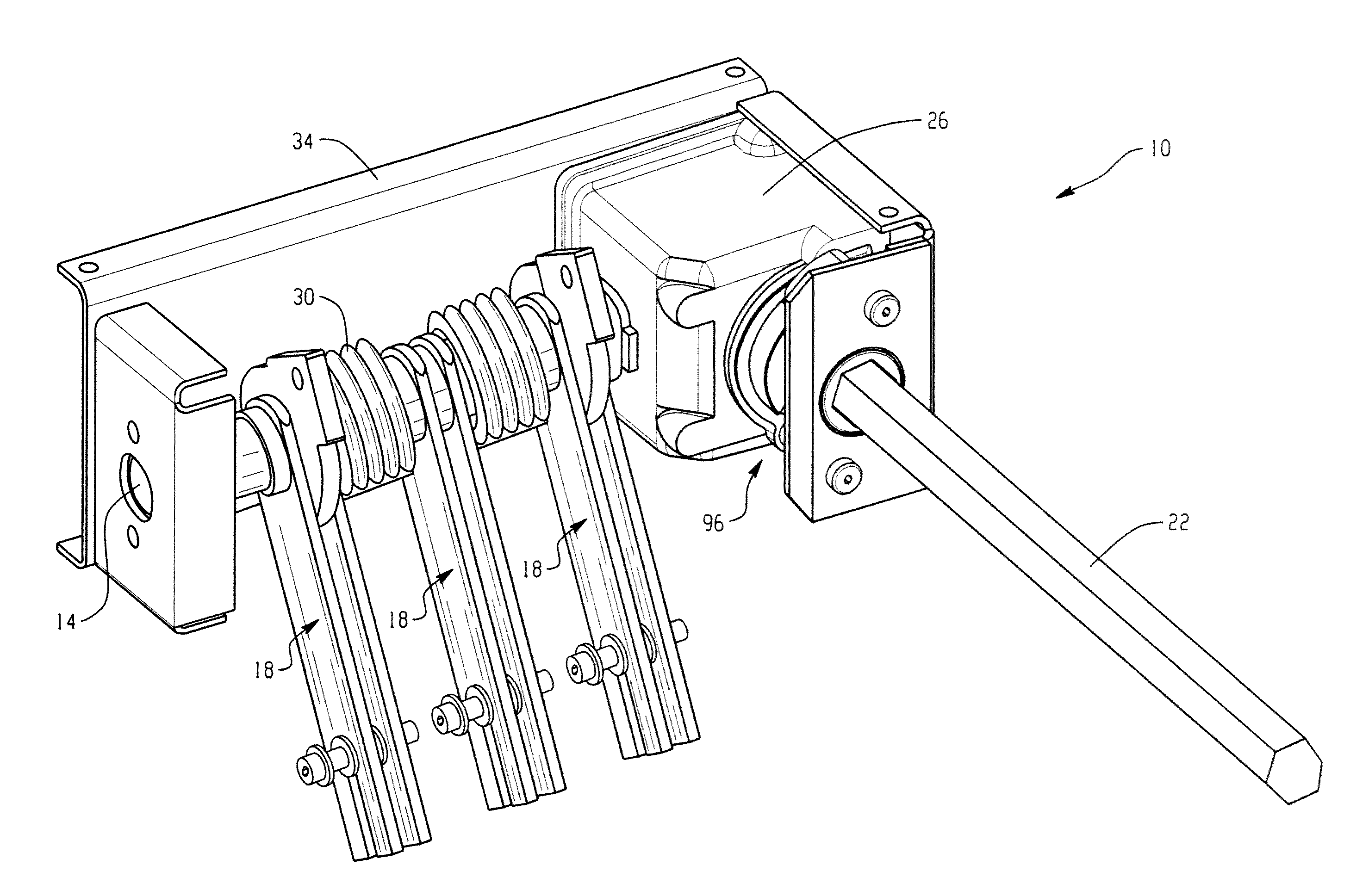
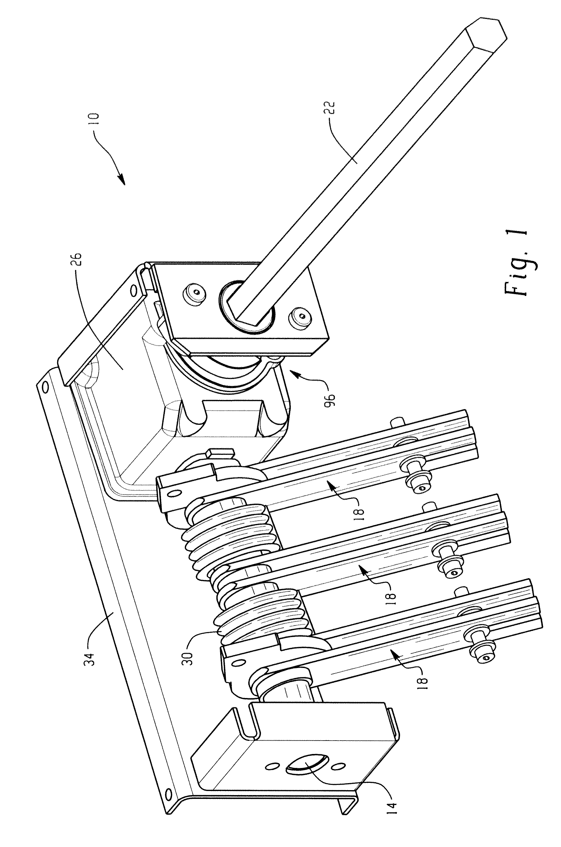
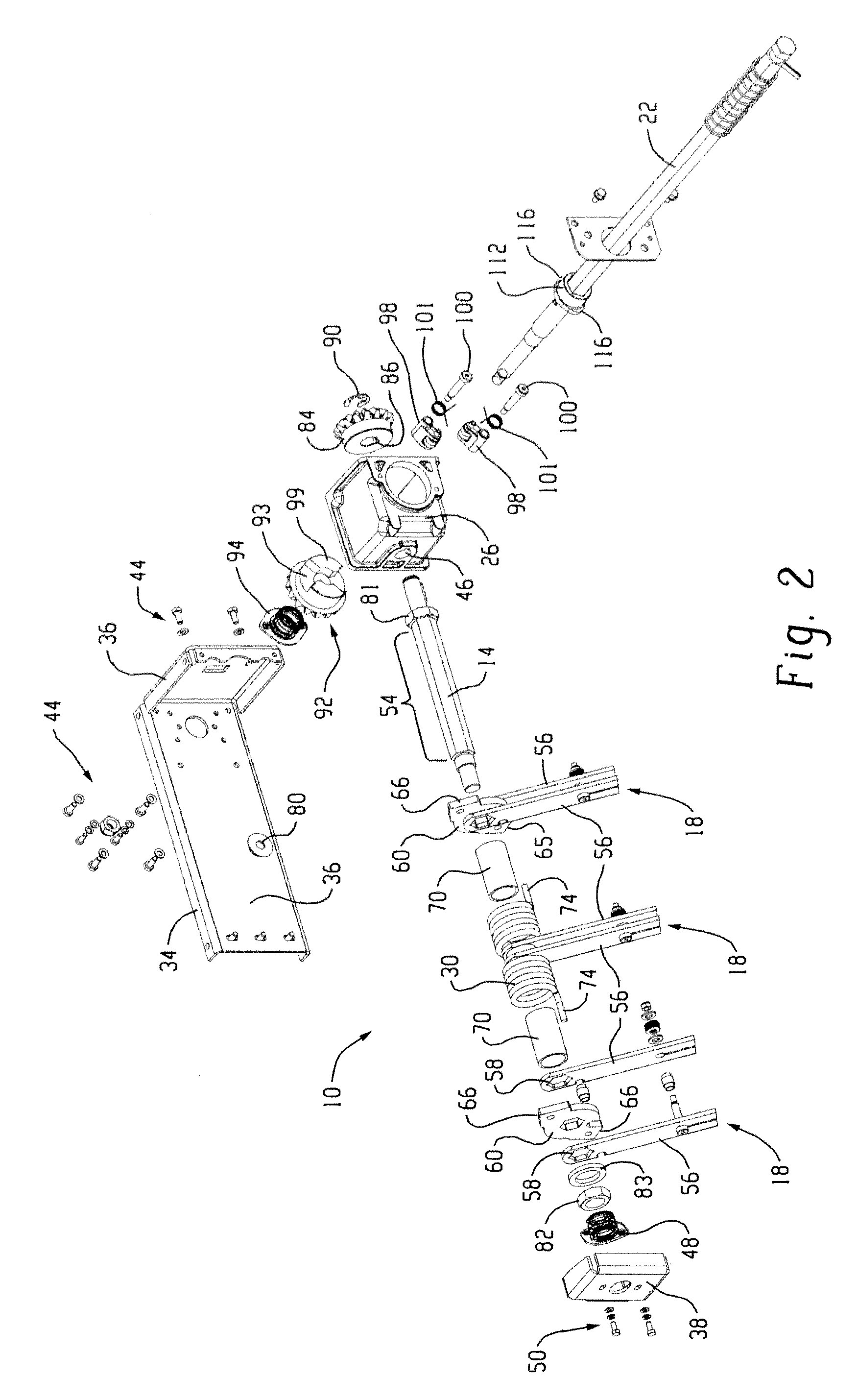
[0023]With reference to FIG. 1, an exemplary earthing switch 10 in accordance with the disclosure is illustrated. The earthing switch 10 generally includes a rotatable actuating shaft 14 on which a plurality of blade contacts 18 are mounted for rotation therewith between an open position and a closed position wherein said contacts 18 engage respective line / load stabs. An actuating mechanism, including an input shaft 22 and gearbox 26, is connected to the actuating shaft 14 for moving the blade contacts 18 between the open and closed positions. Unlike prior art earthing switches that utilize coil-over springs, the earthing switch 10 utilizes a torsion spring 30 arranged coaxially with the actuating shaft 14 for biasing the blade contacts 18 towards the closed position. This results in a compact design that can be easily scaled for various applications. All of the components are supported on a mounting bracket 34 that can be mounted to a desired surface, such as within an electrical c...


PUM


Abstract

A scalable earthing switch that incorporates a torsion spring to effect rapid closure of the switch. The torsion spring is supported coaxially about a rotatable shaft on which contact blades are mounted resulting in compact design. The blade contacts are separated axially along the length of the shaft by one or more spacers. By using difference size spacers the distance between adjacent blade contacts can be changed and, thus, the earthing switch can be easily scaled for different applications. A latching (detent) mechanism is provided for latching the switch in an open position.

Description

BACKGROUND[0001]The present exemplary embodiment relates to electrical switching mechanisms. It finds particular application in conjunction with medium voltage earthing switches, and will be described with particular reference thereto. However, it is to be appreciated that the present exemplary embodiment is also amenable to other like applications.[0002]It is common to provide protection to technicians servicing an electrical component enclosure through the provision of an earthing switch. A typical earthing switch includes one or more blade contacts mounted on a rotatable shaft. An actuating mechanism rotates the shaft to move the blade contacts between an open position and a closed position in contact with a grounding electrode. The earthing switch is typically installed between a distribution bus and a circuit breaker connecting the distribution bus to a main line. The earthing switch, when closed, grounds the distribution bus.[0003]Prior to earthing the line or bus terminals, i...

Claims


Application Information

Patent Timeline
Patent Type & Authority Patents(United States)
IPC IPC(8): H01H5/00H01H31/00H01H1/22H01H1/42H01H1/44H01H31/28
CPCH01H31/003H01H1/42H01H1/44H01H31/28H01H2001/223
Inventor MILLER, DAVID D.
Owner ROCKWELL AUTOMATION TECH
Why Eureka
Try Eureka