Multipurpose, universal converter with battery control and real-time power factor correction

a technology of power factor and converter, which is applied in the direction of emergency power supply arrangement, ac network to reduce harmonics/ripples, transportation and packaging, etc., can solve the problems of incompatibility with the electrical grid a and/or the exact power supply input requirements, energy consumption inefficiency for the us as a whole of over 30%, and achieve fast digital control and feedback, high-hierarchical power energy system, and data acquisition fast

Inactive Publication Date: 2015-11-03
3DFS L L C
View PDF13 Cites 9 Cited by
  • Summary
  • Abstract
  • Description
  • Claims
  • Application Information

AI Technical Summary

Benefits of technology

[0007]In an embodiment, several Converters may be connected together, to power up from the same source, and may work in complete synchronism with each other. In this configuration, a specified phase shift between two or more outputs may be programmed and established. One or more Converters may power a multiple phase grid, or instances of one or more micro-grids, to provide power to a higher hierarchy power energy system. In each of these embodiments, the power generation Converter, with fast data acquisition and fast digital control and feedback, provides syntheses of all required output parameters, with adoptive feedback mechanisms in real time, may supply predictive power management, or may provide adaptive power network compensation. Simultaneously, the converter may provide adaptive Power Factor Correction (PFC) at the time of power generation, to prevent power network overload and distortions.

Problems solved by technology

A variety of generally accepted methods and related equipment currently exist for electric power conversion methods, however they can be incompatible with the electrical grid a and / or the exact power supply input requirements.
The existing AC grid and future development of the AC grid are plagued by extremely low values of Power Factor (PF), resulting from reactive loads as implemented over the past decades of development.
For this reason, PF is mostly never equal to 1, causing energy consumption inefficiency for the US as a whole of over 30% of the consumed energy due to heating dissipation or other dissipative processes.

Method used


Image

  • Multipurpose, universal converter with battery control and real-time power factor correction
  • Multipurpose, universal converter with battery control and real-time power factor correction
  • Multipurpose, universal converter with battery control and real-time power factor correction

Examples


Embodiment Construction

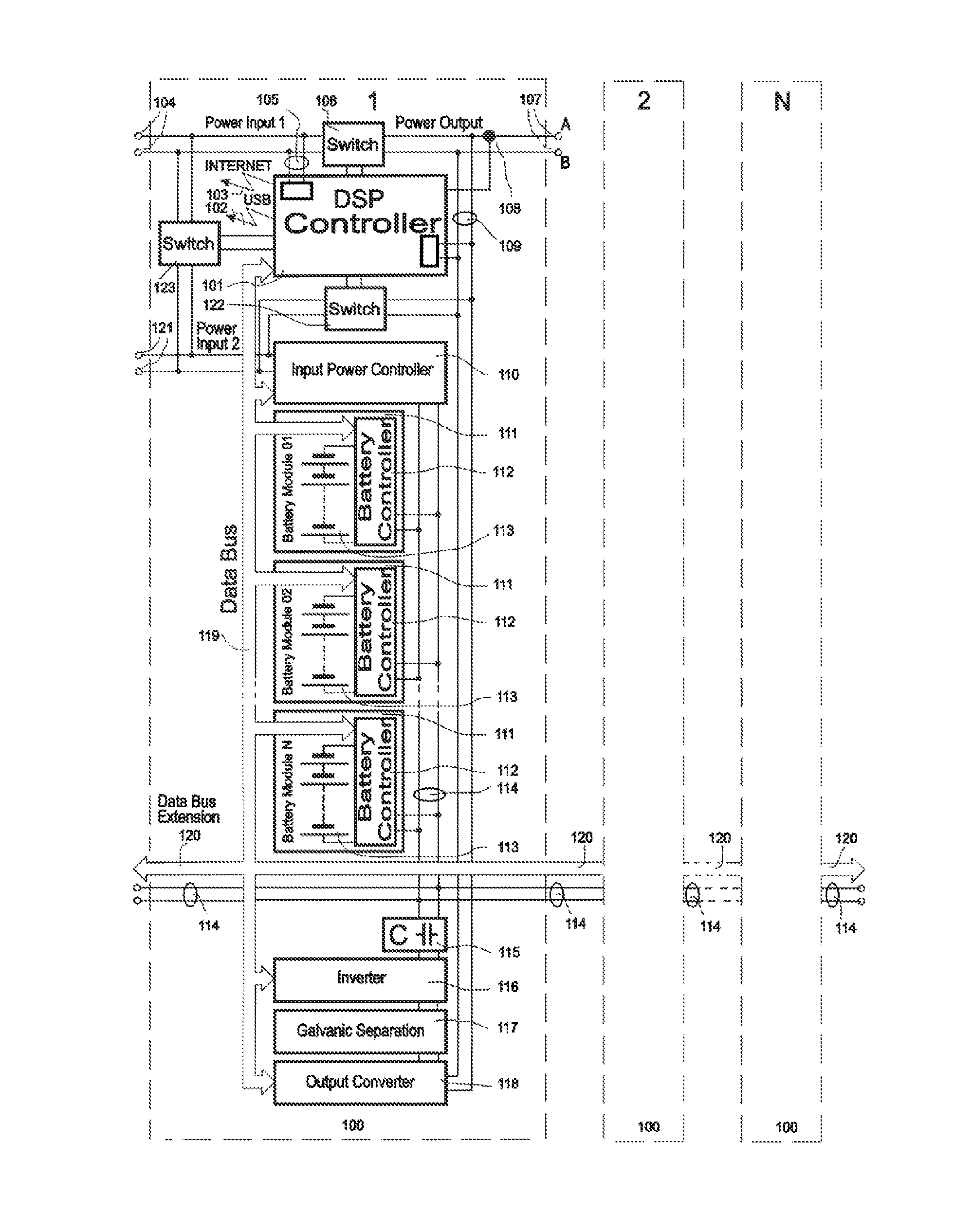
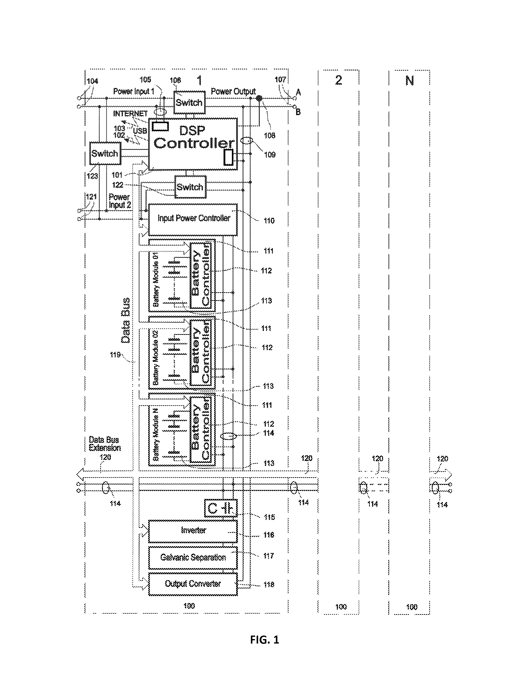
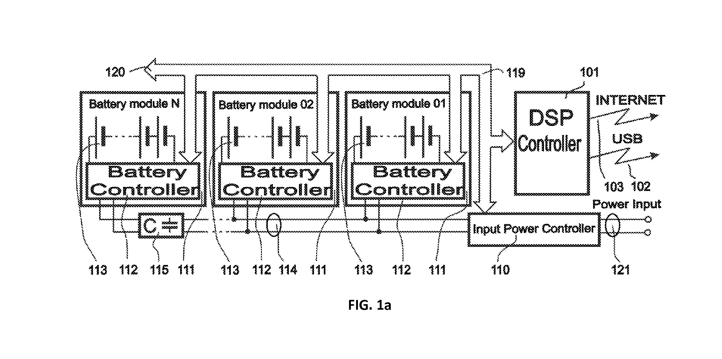
[0015]The multipurpose, universal Converter (converter) consists of several functional modules and contains several stages of conversion, in conjunction with controllers, switches, battery controllers and the connections between these components as shown in FIG. 1. In an exemplary embodiment, the block diagram presented in FIG. 1 serves as a description of the converter in its entirety, but also provides a structural view of component portions that may perform individual functions as a portion of the overall converter structure and without departing from the overall functionality.

Components Description

The main components of the Converter are described herein:

[0016]1. DSP controller. Major functions of the DSP Controller (101) are: to measure input and output power signal parameters utilizing Measuring Circuit (105), Measuring Circuit (109) and the Current Sensor (108) in real time; controlling all components within the Converter and their current modes that provide the desired outpu...


PUM


Abstract

The Electric Power Converter functions as an uninterruptable power supply, battery management, energy conversion, micro-grid formation, and Power Factor Correction including Total Harmonic Distortion correction in real time. Uninterruptable power supply's use is for always-on, real-time, reduced distortion with functions of load reduction and management during peak load events. The Electric Power Converter is able to establish and sustain a micro-grid with multiple and varying sources of power generation and load conditions. The Electric Power Converter achieves dynamic, real-time, interactive Power Factor Correction (PFC) and advanced voltage harmonic distortion correction with a high efficiency ratio. The Electric Power converter is designed to function with the emerging Smart Grid technologies and provide an overall higher level of operating efficiency and higher quality of electrical power.

Description

FIELD OF THE INVENTION[0001]The present invention relates to an apparatus for converting an AC or DC electric input power into DC or AC output with abilities for synchronization with a single or multiphase electric grid, Power Factor Correction (PFC) including Total Harmonic Distortion (THD) correction, an uninterruptable power supply, battery management, battery maintenance, battery storage, energy conversion, electrical grid and micro-grid formation implementation. The invention as disclosed also provides for full control of power conditioning in real time providing correction for multiple different power sources or generators connected to an electrical system.BACKGROUND OF THE INVENTION[0002]A variety of generally accepted methods and related equipment currently exist for electric power conversion methods, however they can be incompatible with the electrical grid a and / or the exact power supply input requirements. Available and widely used AC / DC to DC converters, or AC / DC to AC c...

Claims


Application Information

Patent Timeline
Patent Type & Authority Patents(United States)
IPC IPC(8): H02J1/00H02J3/38H02J7/00H02J9/06H02J3/00H02J3/01
CPCH02J3/01H02J3/381H02J7/0075H02J9/062Y02E40/40Y10T307/62Y02P80/14H02J7/0069H02J2300/10
Inventor OLEYNIK, VLADISLAVALBUL, GENNADY
Owner 3DFS L L C
Why Eureka
Try Eureka