
Method of separating sources in a multisource system

a multi-source system and source technology, applied in the field of telecommunications, can solve the problems of difficult to obtain this data, difficult to know the frequency response of the new link, and disrupt the reception of data signals, and achieve the effect of simple implementation and simplified processing

Active Publication Date: 2015-11-03
FRANCE TELECOM SA
View PDF7 Cites 0 Cited by
  • Summary
  • Abstract
  • Description
  • Claims
  • Application Information

AI Technical Summary

Benefits of technology

This method effectively separates data signals, simplifies processing to correct interference noise, and maintains data integrity without increasing equipment costs, making it suitable for existing telecommunications networks.

Problems solved by technology

These unwanted data signals cause interference that disrupts reception of the data signal intended for the emitting / receiving device.
However, it is difficult to obtain this data, especially when installing a new link or eliminating an existing link or when reinitializing the system.
This difficulty stems from the fact that each emitting / receiving device at the central node and each end user emitting / receiving device receives a plurality of data signals.
It is then difficult to know the frequency response of the new link, for example, because it is impossible to identify the data signal conveyed by the new link among the plurality of data signals received.
Although enabling efficient separation of the various data signals received, such a blind identification method has the drawback of being costly to implement.
All these modifications lead to an increase in the cost of the equipment installed in the telecommunications network.

Method used


Image

  • Method of separating sources in a multisource system
  • Method of separating sources in a multisource system
  • Method of separating sources in a multisource system

Examples


Embodiment Construction

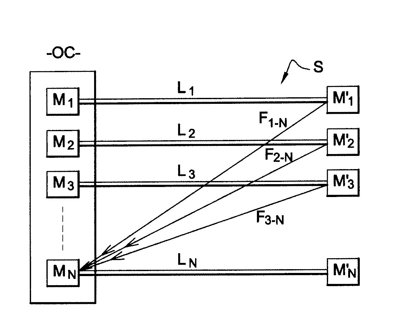
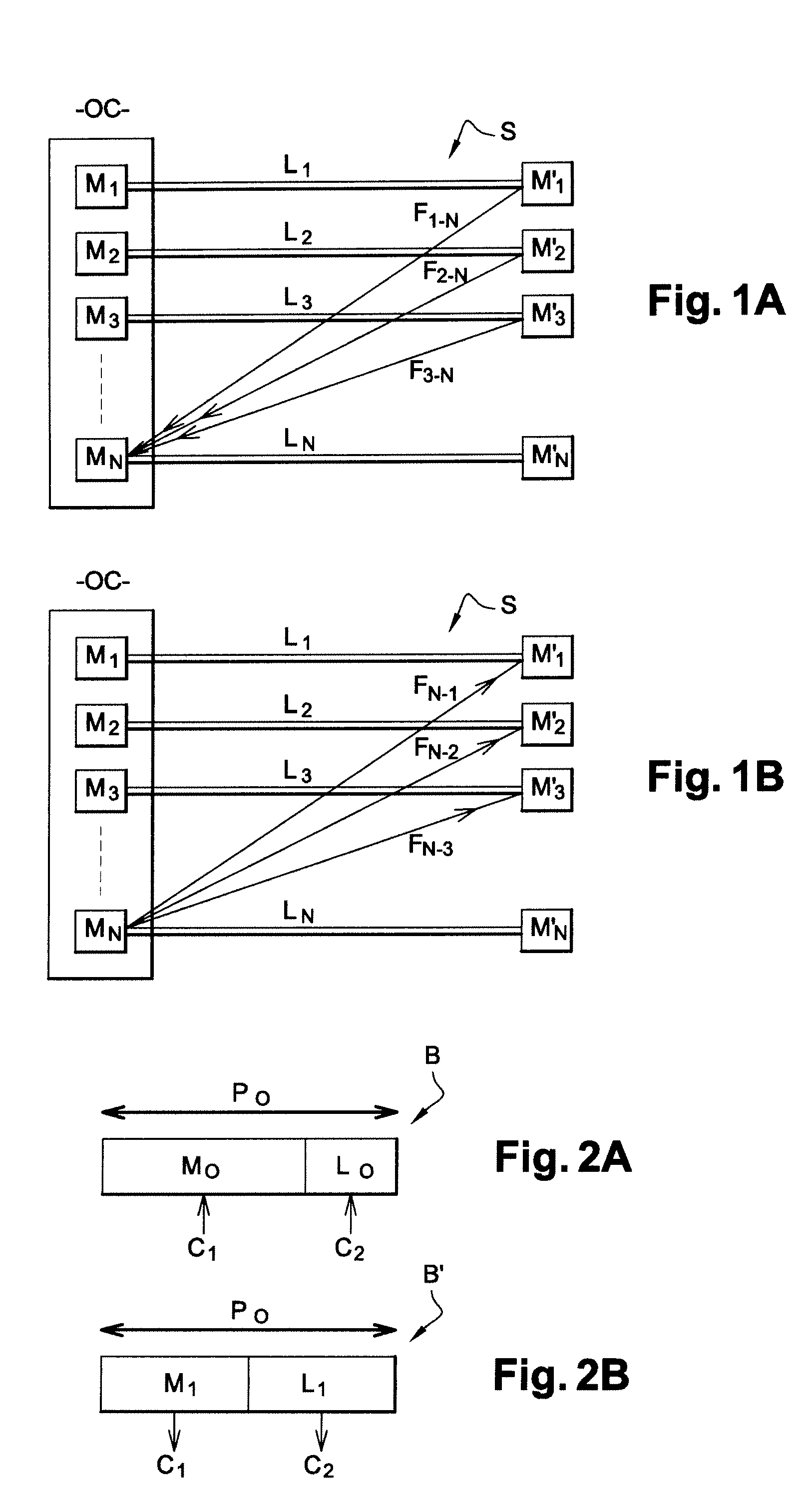
[0053]FIG. 1A represents a communications system S in which the sending and data processing methods of an embodiment of the invention are used. Such a system includes a telephone central office OC including N−1 emitting / receiving devices Di, ε{1, . . . , N−1}. Such devices are xDSL modems, for example. Each modem Di in the telephone central office OC is connected by a link Li to a emitting / receiving device D′i belonging to an end user.

[0054]In a first embodiment of the invention, if the emitting / receiving devices Di in the telephone central office are xDSL modems, the emitting / receiving devices D′i are also xDSL modems. The link Li connecting the modem Di in the telephone central office to the corresponding modem D′i is an xDSL link, i.e. a link enabling transfer of data modulated by the xDSL technique. Such a link Li is a copper line that is part of a cable, for example.

[0055]In a system S such as that described with reference to FIG. 1A, each link Li conveys a signal containing da...


PUM


Abstract

A method is provided for sending at least a first data signal and a second data signal, the data being divided into data blocks of fixed size including a header field of predetermined size, the data signals being sent to at least one data processing device adapted to apply a cyclic autocorrelation function with parameter k enabling the first and second data signals to be identified. The value of the parameter k is a function of a ratio between the size of the data blocks and the predetermined size of the header field. The method includes modifying the size of the header field of the data blocks before sending the first data signal, the value of the parameter k and the size of the data blocks remaining unchanged. A method is also provided for processing signals sent in accordance with the sending method.

Description

CROSS-REFERENCE TO RELATED APPLICATIONS[0001]This Application is a Section 371 National Stage Application of International Application No. PCT / FR2008 / 051362, filed Jul. 18, 2008 and published as WO 2009 / 016306 on Feb. 5, 2009, not in English.STATEMENT REGARDING FEDERALLY SPONSORED RESEARCH OR DEVELOPMENT[0002]None.THE NAMES OF PARTIES TO A JOINT RESEARCH AGREEMENT[0003]None.FIELD OF THE DISCLOSURE[0004]The field of the disclosure is that of telecommunications, more specifically digital data transmission techniques such as xDSL (digital subscriber line) or radio or power line carrier communication transmission techniques. Such techniques can use single-carrier or multi-carrier modulation of the OFDM (orthogonal frequency division multiplex) or DMT (discrete multitone) type.BACKGROUND OF THE DISCLOSURE[0005]In the remainder of the present document, a set of emitting / receiving devices in such a network or system share the same transmission channel to communicate with one another. These...

Claims


Application Information

Patent Timeline
Patent Type & Authority Patents(United States)
IPC IPC(8): H04L5/02H04L27/26
CPCH04L5/023H04L27/2605
Inventor ALAMAYREH, AHMADLE MASSON, JEROME
Owner FRANCE TELECOM SA
Learn More